Facet Layout Diagram (InstanceTopic, 3)
From Hi.gher. Space
Facet Layout Diagram, or FLD, is a diagrammatic notation for defining shapes. It is supposedly capable of uniquely representing all shapes in three or more dimensions that have no curved elements and whose two-dimensional faces are all regular, but this is yet to be proved. It may later be extended to also represent the kinds of shapes it currently cannot.
Understanding FLD
Three dimensions
A circle represents a face. While the color does not matter, it is conventionally yellow. By itself this is therefore the plane.
Two circles joined by a line represents two faces joined by an edge. Therefore by itself this arrangement is two half-planes joined by an edge.
Following the process above, one may generate a facet layout diagram for a 3D shape. So far, if the circles are seen as nodes and the lines as edges, the diagram can be interpreted as the graph of the shape's dual. Therefore the tetrahedron can be represented as follows:
(image here)
However, having a circle for every face in the shape is unwieldy. For this reason, we use the folding technique. Folding consists of identifying a set of circles that are equivalent in the diagram, and turning them into one. By doing this, we end up with several phenomena that are inconsistent with graph theory, hence why we do not say that FLDs are graphs. The first phenomenon is that two circles can be joined by more than one edge. This is demonstrated by the following diagram:
As you can see, three lines join two circles. This actually represents an octahedron, due to parity. While one circle can represent multiple faces, one face cannot be represented by multiple circles, even if they are equivalent in the diagram. If this were a tetrahedron, you could pick a vertex and go around it, ending up going from left to right to left to right on the diagram but ending back where you started on the tetrahedron itself.
The number of lines touching a circle can be seen as the number of edges around that face. However, one can label a circle with a number to indicate that the lines touching it should be replicated that many times. Therefore the example above can be redrawn as:
This must be done with care, though, as it only means they should be replicated when moving from the labelled circle in question, not to it. To demonstrate this, observe the following example.
The numbers on each side of a line are different, but this is perfectly valid: in fact, this shape is the cuboctahedron. Each circle has one line from it, so the "3" circle has 1*3 = 3 sides and the "4" circle has 1*4 = 4 sides. So the "3" circle represents the triangles and the "4" circle represents the squares. The fact that there is only one line in the diagram indicates that all edges in the cuboctahedron are equivalent: they each join a triangle to a square.
Now, back to our example with the octahedron. The next concept to introduce is the bounce line (alternatively end line, reverse line, terminating line etc.). A bounce line is represented by a line coming from a circle and ending at a "Y" figure. By creating a bounce line we can fold the octahedron diagram once more:
The bounce line indicates a symmetric edge: an edge which links two equivalent faces. However, we now have a problem. Recall the reason for the original diagram representing an octahedron: parity. All the diagram told us was that there were triangular faces each joined to other triangular faces and that there was an even number of triangles around a vertex. This could be a degenerate triangle, a triangular tiling of the plane, or any one of an infinite number of hyperbolic tilings for all we know.
To solve this problem, we use a bounce label (alternatively outer label), a number written next to a bounce line indicating how many times you can follow that bounce line in the same direction to return to where you started.
How many bounce lines are there on the above diagram? You may of course say "one" immediately, but you need to remember that there are three, as the "3" label indicates all lines touching that circle must be replicated that many times. In the case that there is only one bounce line on a given circle (after replication, of course), no bounce label is necessary as it can only be a "2".
The above diagram represents an octahedron, as you need to go through exactly four triangles (taking the same direction each time) to get back to where you started. Similarly, a tetrahedron and icosahedron have the same diagram, except with bounce labels of "3" and "5". As you can see, the bounce label in this case acts as part of a Schlaefli symbol by telling you how many instances of that face you will find around a vertex of the face. However, there are other cases (such as antiprisms) where it does not, so it should not be confused with this concept.
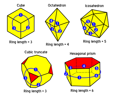
If you are still having difficulty finding out what a bounce label should say, remember it's equal to the ring length through adjacent instances of a face:
There is one final point to note in three-dimensional FLD. When there are three or more unique lines touching any given circle, the order in which they touch the circle matters, as this is the same order the edges appear on the actual face.
Full example
Let's say we want to find the FLD of the cuboctahedral rectate (the Ko5). A quick first glance at the shape tells us that it is made of triangles and squares. However, we must realize that there are two types of squares on the Ko5 - some squares are uniform (each edge of the square is equivalent), whereas the other squares only have opposite edges equivalent, and adjacent edges unique. Conversely, looking at the triangles, we see that all the triangles are equivalent, and all the edges of each triangle are also equivalent. Therefore, we have established there are exactly three unique faces: the triangle, the uniform square, and the non-uniform square. So we know we will need exactly three circles in our diagram.
Now the triangle and uniform square can be represented by a circle labelled "3" and "4" respectively with one line touching each. This establishes the number of edges on each face, and also that the edges within each face are equivalent. For the remaining face, the non-uniform square, we look at the edges in order, and observe the faces on the other side of each edge go "3-4-3-4", where the "3" is our triangle and the "4" is our uniform square. This can be rewritten as "2(3-4)" (note that "3-3-4-4" cannot be condensed to anything shorter; the entire pattern inside the brackets is replicated, not the numbers themselves). Thus the "2" is the number that we should label our final circle with, and the "3" and the "4" are what it should connect too. We end up with the following diagram:
On reading the diagram, we start at the leftmost circle, the "3", by convention, and notice that we have a uniform triangle in our shape. We then follow the line to the "2", and see that it must be a square, as 2x2 = 4. We follow the line to the "4", and see that we have a uniform square connected to the non-uniform square. Now we follow it back through the "2" again to the "3". So far, we have travelled over four lines in the same direction, meaning the shapes we have uncovered (triangle, square, square, square) appear around a vertex of the shape. By following the other paths available from each node (imagining the replication has been carried out; there are indeed only two lines on the diagram itself), we fill in the other faces on the shape until we have a complete realmic boundary with no gaps.
