It took me some time, but I got it. Saw it for the first time about 4 years back, now I want to share it.
We all know that the cyltrianglinder is produced from rotating a trianglinder ( triangle prism ) around into the W-axis of the fourth dimension. When this happens, the triangle ends are being whipped around in a circular path into 4-D. This motion traces out a continuous rolling surface of a triangle torus. Similar to the classic "cube rotating inside-out" videos (depicting the rotation of a tesseract) that we've probably all seen, the trianglinder also has this same motion applied. Except for this time, visualize the triangle ends as the sides moving inside out. The square panels spin in place, but the triangle panels are being extruded along a circular path, joining into a torus.
There are four side panels on a cyltrianglinder, each of which are an entire 3-D shape. The 3 SQUARE panels of a trianglinder undergo a regular spin creating the 3 CYLINDERS. These 3 cylinders are the flat surface panels, the TRIANGLE TORUS is the 3-sided curved rolling surface.
When the cyltrianglinder's rolling surface sits on our 3-D plane, it's contact patch is in the shape of a triangle. The cyltrianglinder can roll along any direction perpendicular to the 3 sides of this triangle. Much like a cylinder can roll along a perpendicular direction to its line contact patch.
It is essentially a circle attached to every point of a triangle. By embedding a circle into every point of a triangle, we see the proper analogy realized: The CYLINDER is a side panel, the CIRCLE is a vertex, and the TRIANGLE TORUS is the rolling surface connecting all curved surfaces of the cylinders together.
Cross sections of the cyltrianglinder :
- Slicing along the rolling surface, we see a TRIANGLE expanding to a TRIANGLINDER, then collapse back into a TRIANGLE. ( This follows the pattern of a cross section flow through a cylinder: Starting with the LINE ( contact patch ), it expands into a SQUARE, then collapses back into a LINE )
- Slicing through the flat cylinder panels, we see a CYLINDER collapse to a CIRCLE and vice versa. (This pattern is identical to the cross section flow through a triangle : starting with a LINE at the base, it collapses to a POINT and vice versa )
Over the last 5 years, I have developed a mathematical calculation format for constructing n-D shapes, called Dimensionometry, short for dimensional geometry. The left column represents the surface panel breakdown of a starting shape, second column is the operation matrix, right column are the final product surface panels. The rows represent the direct transformation of the surface panels by their respective operation.
These illustrate the growth of a line into a cyltrianglinder:
LINE = |
[ * ] ----x---> [ * ] == [ | ] --- This is read as " POINT extruding to a POINT along X equals the DOT-PRISM, or LINE"
----------------------------------
[ *:x ] ------> [ * ] == [ *2:x ] --- " POINT of X connecting to POINT equals POINT pair on X " , the surface elements of a LINE
TRIANGLE = |>
[ | ] ---y--> [ * ] == [ |> ] --- Read as "LINE tapering to POINT along Y equals TRIANGLE"
---------------------------------
[ *2:x ] ---> [ * ] == [ |2:x ] --- Read as "POINT pair of X connecting to POINT along Y equals LINE pair on X"
----------------------- [ |-*:y ] --- read as "LINE paired with POINT on Y"
TRIANGLINDER = |>|
[ |> ] --z--> [ |> ] == [ |>| ] --- "TRIANGLE extrudes to TRIANGLE along Z equals TRIANGLINDER"
-------------------------------------
[ |2:x ] ---> [ |2 ] == [ ||2:x ] --- "LINE pair of X connects to LINE pair equals SQUARE pair of X"
[ |-*:y ] --> [ |-* ] == [ ||-|:y ] --- " LINE-POINT pair of Y connects to LINE-POINT pair equals SQUARE-LINE pair of Y"
-------------------------- [ |>2:z ] --- " TRIANGLE pair of Z"
CYLTRIANGLINDER = |>|0
[ |>| ] ---w---> [ 0z ] == |>|0 --- "TRIANGLINDER spun into W where Z is EQUATORIAL ( torus transformation ) equals CYLTRIANGLINDER"
--------------------------------------------
[ ||2:x ] ------> [ 0 ] == [ ||02:x ] --- " SQUARE pair of X [spun as POLAR] equals CYLINDER pair of X "
[ ||-|:y ] -----> [ 0 ] == [ ||0-|0:y ] --- " SQUARE-LINE pair of Y [spun as POLAR] equals CYLINDER-CIRCLE pair of Y"
[ |>2:z ] ----> [ (0) ] == [ |>xy(0):zw ] --- " TRIANGLE pair of Z [spun as EQUATORIAL] equals TRIANGLE (of XY plane) EXTRUDED -along path of- CIRCLE ZW "
- Philip
Understanding the Cyltrianglinder
18 posts
• Page 1 of 1
Understanding the Cyltrianglinder
![]() by ICN5D » Fri Nov 15, 2013 9:16 pm
by ICN5D » Fri Nov 15, 2013 9:16 pm
It is by will alone, I set my donuts in motion
- ICN5D
- Pentonian
- Posts: 1135
- Joined: Mon Jul 28, 2008 4:25 am
- Location: the Land of Flowers
Re: Understanding the Cyltrianglinder
![]() by wendy » Sat Nov 16, 2013 8:28 am
by wendy » Sat Nov 16, 2013 8:28 am
It's a triangle-circle prism, in common parlence.
The dream you dream alone is only a dream
the dream we dream together is reality.
\ ( \(\LaTeX\ \) \ ) [no spaces] at https://greasyfork.org/en/users/188714-wendy-krieger
the dream we dream together is reality.
\ ( \(\LaTeX\ \) \ ) [no spaces] at https://greasyfork.org/en/users/188714-wendy-krieger
-

wendy - Pentonian
- Posts: 2031
- Joined: Tue Jan 18, 2005 12:42 pm
- Location: Brisbane, Australia
Re: Understanding the Cyltrianglinder
![]() by Klitzing » Sat Nov 16, 2013 9:52 am
by Klitzing » Sat Nov 16, 2013 9:52 am
@Wendy: rather a (triangle,circle)-duoprism
@Philipp: by "trianglinder" you probably mean the well-known triangle-prism
--- rk
@Philipp: by "trianglinder" you probably mean the well-known triangle-prism
--- rk
- Klitzing
- Pentonian
- Posts: 1649
- Joined: Sun Aug 19, 2012 11:16 am
- Location: Heidenheim, Germany
Re: Understanding the Cyltrianglinder
![]() by ICN5D » Sat Nov 16, 2013 5:49 pm
by ICN5D » Sat Nov 16, 2013 5:49 pm
Yes, I am referring to the triangle prism when I use the word trianglinder. Because it's different, I like to put it in parentheses on the first mention, just to ensure we're on the same page. Like many, I have refashioned some of the nomenclature only to my personal liking. But the word " trianglinder" is very descriptive in it's nature, is it not? Etymologically speaking, it does describe the shape quite well. That is, once one has derived the root words of "cylinder", by breaking it down to cy-lin-der as the spin of the line prism.
It is by will alone, I set my donuts in motion
- ICN5D
- Pentonian
- Posts: 1135
- Joined: Mon Jul 28, 2008 4:25 am
- Location: the Land of Flowers
Re: Understanding the Cyltrianglinder
![]() by wendy » Sun Nov 17, 2013 10:09 am
by wendy » Sun Nov 17, 2013 10:09 am
The general class of X Y prisms, cut a shape X from the w-x space, and Y from the y-z space, cylinders are a kind of prism. You get so many shapes that giving them funny names does not really work.
cylinder breakes down to cyl (as in cycle), and inder.
cylinder breakes down to cyl (as in cycle), and inder.
The dream you dream alone is only a dream
the dream we dream together is reality.
\ ( \(\LaTeX\ \) \ ) [no spaces] at https://greasyfork.org/en/users/188714-wendy-krieger
the dream we dream together is reality.
\ ( \(\LaTeX\ \) \ ) [no spaces] at https://greasyfork.org/en/users/188714-wendy-krieger
-
wendy - Pentonian
- Posts: 2031
- Joined: Tue Jan 18, 2005 12:42 pm
- Location: Brisbane, Australia
Re: Understanding the Cyltrianglinder
![]() by Keiji » Sun Nov 17, 2013 10:34 pm
by Keiji » Sun Nov 17, 2013 10:34 pm
Hi ICN5D, and congratulations for working out what you have.
Please don't be upset if I ask you to stop there, though: you're going through the same thought processes I did years ago, thinking of objects being "extruded", "tapered" or "lathed" (spun round an axis). While these apply quite nicely to the classic rotatopes, they don't generalise well to other shapes.
The cyltrianglinder is the Cartesian product of a triangle and a circle.
I've been thinking about it for a bit, and although I'm pretty sure you can't lathe a triangular prism to get a cyltrianglinder, I can't prove it off the top of my head. If you can, I'd love to see how.
The important thing is that not all objects directly map onto a linear "take base shape, perform operation X, perform operation Y, perform operation Z" construction. Sometimes you have to use a product, such as "take base shape, perform operation X, call this R, now start again and perform operation Y, call this S, now take product of R and S." - and you can't just rewrite the latter in the former notation. A good case in point is the powertopes - if you take for example the octagon of a circle, you can represent that as the octagonal brick product of a circle and another circle, and if you really wanted to you could write each circle as "a line lathed", but you cannot say that the octagon of a circle is the same as a line lathed then octagon'd then lathed again, or the like.
So in conclusion - a cyltrianglinder is square{triangle,circle}, and should not be represented without using some form of product - you will need to incorporate the concepts of products into your "dimensionometry" otherwise you will be excluding or misrepresenting a lot of objects that have already been discovered.
Having said all that, if you can adjust your algorithms so that they work with products, there is still a lot to learn about higher dimensional geometry - my ultimate goal at the moment is to find an algorithm to calculate the incidence matrix of the generalised brick product given the source objects' incidence matrices, for example - and I'm all ears to new ideas
-

Keiji - Administrator
- Posts: 1985
- Joined: Mon Nov 10, 2003 6:33 pm
- Location: Torquay, England
Re: Understanding the Cyltrianglinder
![]() by Klitzing » Sun Nov 17, 2013 11:37 pm
by Klitzing » Sun Nov 17, 2013 11:37 pm
Hi Keiji,
not too hard at all, just depends on the generalization you have in mind.
So e.g. for the product of 2 regular polytopes, it just runs like that:
Providing a simple example: the searched for incidence matrix of the duoprism (= product) of the cube (o3o4x) and the octahedron (x3o4o):
--- rk
not too hard at all, just depends on the generalization you have in mind.
So e.g. for the product of 2 regular polytopes, it just runs like that:
- The count of vertices of the product is just the product of the counts of vertices of the components.
- For edges you'll get 2 types: either point times edge or edge times point. Their counts are accordingly the count of vertices of the first component times the count of edges of the second. And for the other ones vice versa.
- For faces then you get 3 possibilities: vertices times faces, edges times edges, faces times vertices. The respective counts then are obtained similarily.
- The same principle runs through for all the next dimensions, each time one further possibility - at least as long the required ones of the components would exist. This is why that number of different cases ultimately decreases again.
Providing a simple example: the searched for incidence matrix of the duoprism (= product) of the cube (o3o4x) and the octahedron (x3o4o):
- Code: Select all
x3o4o o3o4x

. . . . . . | 48 |  4  3 |  4  12  3 | 1 12 12 1 |  3 12  4 | 3 4   v * v
------------+----+-------+-----------+-----------+----------+----
x . . . . . |  2 | 96  * |  2   3  0 | 1  6  3 0 |  3  6  1 | 3 2   e * v
. . . . . x |  2 |  * 72 |  0   4  2 | 0  4  8 1 |  1  8  4 | 2 4   v * e
------------+----+-------+-----------+-----------+----------+----
x3o . . . . |  3 |  3  0 | 64   *  * | 1  3  0 0 |  3  3  0 | 3 1   f * v
x . . . . x |  4 |  2  2 |  * 144  * | 0  2  2 0 |  1  4  1 | 2 2   e * e
. . . . o4x |  4 |  0  4 |  *   * 36 | 0  0  4 1 |  0  4  4 | 1 4   v * f
------------+----+-------+-----------+-----------+----------+----
x3o4o . . . |  6 | 12  0 |  8   0  0 | 8  *  * * |  3  0  0 | 3 0   etc.
x3o . . . x |  6 |  6  3 |  2   3  0 | * 96  * * |  1  2  0 | 2 1
x . . . o4x |  8 |  4  8 |  0   4  2 | *  * 72 * |  0  2  1 | 1 2
. . . o3o4x |  8 |  0 12 |  0   0  6 | *  *  * 6 |  0  0  4 | 0 4
------------+----+-------+-----------+-----------+----------+----
x3o4o . . x | 12 | 24  6 | 16  12  0 | 2  8  0 0 | 12  *  * | 2 0
x3o . . o4x | 12 | 12 12 |  4  12  3 | 0  4  3 0 |  * 48  * | 1 1
x . . o3o4x | 16 |  8 24 |  0  12 12 | 0  0  6 2 |  *  * 12 | 0 2
------------+----+-------+-----------+-----------+----------+----
x3o4o . o4x | 24 | 48 24 | 32  48  6 | 4 32 12 0 |  4  8  0 | 6 *
x3o . o3o4x | 24 | 24 36 |  8  36 18 | 0 12 18 3 |  0  6  3 | * 8
--- rk
- Klitzing
- Pentonian
- Posts: 1649
- Joined: Sun Aug 19, 2012 11:16 am
- Location: Heidenheim, Germany
Re: Understanding the Cyltrianglinder
![]() by wendy » Mon Nov 18, 2013 9:36 am
by wendy » Mon Nov 18, 2013 9:36 am
Still don't know where richard picked 'duoprism' from. It's always been prism by me: you can have a product of three or more bases, and it's still a prism.
The dream you dream alone is only a dream
the dream we dream together is reality.
\ ( \(\LaTeX\ \) \ ) [no spaces] at https://greasyfork.org/en/users/188714-wendy-krieger
the dream we dream together is reality.
\ ( \(\LaTeX\ \) \ ) [no spaces] at https://greasyfork.org/en/users/188714-wendy-krieger
-
wendy - Pentonian
- Posts: 2031
- Joined: Tue Jan 18, 2005 12:42 pm
- Location: Brisbane, Australia
Re: Understanding the Cyltrianglinder
![]() by Klitzing » Mon Nov 18, 2013 1:26 pm
by Klitzing » Mon Nov 18, 2013 1:26 pm
This is the Johnson type nomenclatura, also taken over by Olshevsky, and then by Bowers. As such it got integral content of both the long names and thus likewise his acronyms (OBSAs = official Bowers style acronyms).
If we had (with P some irreducible polytope, dim(P) > 1, L being a mere edge (line element))
But you are right in that the mere product operation in all cases would be the same. Moreover it would be both associative and commutative. It variously is known as direct sum, as cartesian product, or as your prism product.
--- rk
If we had (with P some irreducible polytope, dim(P) > 1, L being a mere edge (line element))
- P' = P x L --> P-prism (OBSA: -(i)p)
- P' = P1 x P2 --> (P1,P2)-duoprism (OBSA: -dip)
- P' = P1 x P2 x L --> (P1,P2)-duoprismatic prism (OBSA: -dippip)
- P' = P1 x P2 x P3 --> (P1,P2,P3)-triprism (OBSA: -tip)
- etc.
But you are right in that the mere product operation in all cases would be the same. Moreover it would be both associative and commutative. It variously is known as direct sum, as cartesian product, or as your prism product.
--- rk
- Klitzing
- Pentonian
- Posts: 1649
- Joined: Sun Aug 19, 2012 11:16 am
- Location: Heidenheim, Germany
Re: Understanding the Cyltrianglinder
![]() by ICN5D » Tue Nov 19, 2013 4:38 am
by ICN5D » Tue Nov 19, 2013 4:38 am
@ Keiji: Hey, thanks for taking your time to respond. I like your input about new additions to my little creation. A side effect of self-teaching and development outside other academic sources can lead it to be radical and incomplete. I am a 30 year old professional bicycle mechanic and this is my side hobby. I am quite aware that there are infinite shapes in any dimension, many of which can be described by the processes that are discussed here. Judging by my joining date, you can tell I've been away for some time.
Although, I am unsure as to why you would ask me to stop. I am not disproving anything said on the forum, nor am I spreading disinformation. I bring new ideas and methods, to an appropriate forum where these things are being discussed. It's not off topic, not harassing, not vulgar or full of uneducated "text speak". Collaborating ideas is how ideas grow. Perhaps you will find some value to my outside perspective. Maybe you find my username " ICN5D " to have a dose of mild arrogance, thus ruining any beneficial first impression, I don't know. I do not claim to know everything, you know more than I do in this topic. I'm the guy who fixes your $10,000 racing bicycle, you are the admin for HDDB.
So, think of it as an an alternative path to "enlightenment" to aid in sharpening one's visual acuity above 3-D. It is a very basic form of what many of you are talking about. It definitely does not include powertopes and the like. It can be used as an introductory education tool to prepare for the other material on HDDB. The goal was to educate and familiarize people who have never thought about these things or wondered what the heck a tesseract really was. Being that it is a simplified linear construction language, shapes above 4-D can still be grasped even by the most non-mathematical types.
As for proving the transformation of a triangle prism into what I call the cyltrianglinder: I'm still kicking myself in the butt for not taking calculus in high school. I know that it is a very powerful tool for such things. If you are referring to the word "lathe" as my "spin" motion, then I can try. However, as stated above, I have developed my own proof system using the graphical matrix computation format. I designed it to be easily understood by any mathematically minded person with an eye for patterns. If you are asking me for help, then maybe you see something of value to it! It has helped me teach myself. Mathematics ( other than statistics) is an exact thing, no shades of gray. And because of that, there is always an exact solution, something to strive for in conceptual hurdles. Below is going to be a verbose, heavy read as I attempt to explain my thought process after 5 and a half years of familiarity.
In order to do so, I have to walk you through the some of the same steps I took. The way I calculate shapes is by reducing them into their N-1 surface panels and pairing them up on a particular axis. I felt there was no need to identify whether the pair was attached on a triangular-like shape, like the line torus on a cone as being attached at the vertex. The simplicity of Dimensionometry allows me to do this with every shape for consistency.
0 = spin ( lathe )
> = taper ( scale )
| = extrude ( translate )
(0) = extrude along path of line that has been spun, i.e: circle
* = vertex
Applying the extrude or taper is very straightforward, but the spin is tricky. When I visualize an object spinning around in place into the N+1, I see some of the N-1 surface panels undergo different motions. Some side panel pairs sit in place and apply the spin ( lathe ) motion, while only one pair joins together into a torus. I use the terms POLAR and EQUATORIAL to denote them. Much like how our planet spins around, at the equator an object is flung around in a great big circle, tracing out the path of a "circular extrusion " of a manifold. Whereas at the geometric poles, an object more or less sits in place and rotates ( lathes ). This is of course an oversimplified visual trick to identify which sides spin and which become a torus. After some time, I noticed that in this method, there are 3 types of spins ( and perhaps even more). I named them PRISMIC, TRIANGULAR, and SPHERICAL spins. The difference is how and where to apply polar vs equatorial.
PRISMIC SPIN : equatorial applied to last extruded pair in the sequence
TRIANGULAR SPIN : eqtrl applied to second last created pair, one of the connecting sides between base and vertex
SPHERICAL SPIN : eqtrl applied evenly to entire surface, no polar pairs
Consider how the square, " || " spins into 3-D to trace out the shape of a cylinder. The square has four lines on its surface, as two pairs separated by the x and y axes. When I say "on the x-axis", I really mean "separated by/along the x-axis". My symbols for these are:
" |2:x " = line pair on X
" |2:y " = line pair on Y
So, || = [ |2:x , |2:y ]. Since a square has only two pairs, applying the spin operation means one line pair becomes POLAR and the other EQUATORIAL. (Above 3-D I found that only one pair can be equatorial, but many can be polar.) The polar line-pair sits in place and spins to trace out a circle-pair, " |02 ". The equatorial line-pair is flung around in a circle, and therefore extruded along the path of a circle, joining to create a line-torus " |(0) ". This symbol " |(0) " means " line extruded along the path of a circle". The spin operation in parentheses is the modifier of the default extrude, meaning extruded along the path of a line that has been spun. This gives us two circles attached by a line torus, which agrees with what we see as the surface of a cylinder. The graphical representation is like this:
[ || ] --z--> [ 0y ] == [ ||0 ] --- " square ---> spins into Z == cylinder " , where the y-axis pair is equatorial
--------------------------------------
[ |2:x ] ---> [ 0 ] == [ |02:x ] --- " line pair of x ---> spins == circle pair "
[ |2:y ] --> [ (0) ] == [ |(0):yz ] --- " line pair of y ---> extrudes along path of circle == line torus"
Extruding a circle also creates the cylinder:
[ |0 ] ----z---> [ |0 ] == [ |0| ] --- " circle ---> circle = cylinder "
----------------------------------------
[ *(0):xy ] --> [ *(0) ] == [ |(0):xy ] --- " dot-torus ---> dot-torus = line-torus " , the dot-torus is the n-1 wireframe surface of a circle **
----------------------------- [ |02:z ] --- final pair is circle to circle along z, which creates the cylinder
** The torus transformations have a partial distributive law, where only the sub-shape is modified and the manifold left alone. However, during a spherical spin the manifold is modified and the sub-shape is left alone.
Spinning a cube into 4-D traces out the shape of a cubinder, or cylinder-prism. Since a cube has 6 square sides, there are 3 pairs of squares on their respective axes. During the spin, only one pair is equatorial, the rest as polar. So, CUBE : [ ||| ] = [ ||2:x , ||2:y , ||2:z ]
Graph detailing the spin of the cube:
[ ||| ] --w--> [ 0z ] == [ |||0 ] --- " cube ---> spin into W == cubinder, where z-pair is equatorial"
----------------------------------------------
[ ||2:x ] -----> [ 0 ] == [ ||02:x ] --- " square pair of x ---> spin == cylinder pair of x "
[ ||2:y ] -----> [ 0 ] == [ ||02:y ] --- " square pair of y ---> spin == cylinder pair of y "
[ ||2:z ] ---> [ (0) ] == [ ||(0):zw ] --- " square pair of z ---> extruded along path of circle zw == square torus "
When looking at the projection of a cubinder, we see a cylinder within a cylinder, attached by two more cylinders and a square torus. Another calculation of the cubinder is the extrusion of the cylinder: [ |||0 ] = [ ||0| ] = [ |0|| ]
[ ||0 ] ---w---> [ ||0 ] == [ ||0| ] --- " cylinder ---> extruded along w to cylinder == cubinder "
---------------------------------------------------
[ |(0):xy ] ---> [ |(0) ] == [ ||(0):xy ] --- " line torus --> line torus == square torus " , line --> line = square, the manifold isn't modified
[ |02:z ] ------> [ |02 ] == [ ||02:z ] --- " circle pair ---> circle pair = cylinder pair "
-------------------------------- [ ||02:w ] --- final pair is how shape was made, cyl-pair joined along w creates cubinder
In both graphs, the end result is that a cubinder has four cylinders attached by a square torus. Both the spin of the cube and extrude of the cylinder agree in the same n-1 surface panels. Another description is the Cartesian product of a square and a circle.
Here we apply the spin to a triangle-prism. Another way to create the cyltrianglinder ( god I love that word ), is to taper a cylinder down to a circle along the W-axis. This method is identical to tapering a line to a point, it is simply the same version where a circle is embedded into every point.
The triangle-prism : [ |>| ] , extrude of triangle along Z, or taper of square to line along Z.
[ |> ] --z--> [ |> ] == [ |>| ]
-----------------------------------
[ |2:x ] ---> [ |2 ] == [ ||2:x ]
[ |-*:y ] --> [ |-* ] == [ ||-|:y ]
-------------------------- [ |>2:z ]
[ || ] ---z--> [ | ] == [ |>| ] --- " square --> line along Z = triangle-prism"
---------------------------------
[ |2:x ] ---> [ *2 ] == [ |>2:x ] --- " line-pair --> point-pair = triangle-pair" , viewing a line from the x-axis we see it from it's natural 1-D perspective, two points
[ |2:y ] ----> [ | ] == [ ||2:y ] --- " line-pair --> line = square-pair" , viewing the line from above & below in y-space, seeing it it from a higher perspective, a line
------------------------- [ ||-|:z ] -- " final pair is the square-line pair, to account for the last square on surface unaccounted for
Spinning, or lathing a triangle-prism is the process of rotating |>| as if it were "flat", which it is according to 4-D. Since the two triangle ends are considered the final extruded pair, I assign them as equatorial. Associating any other side panel pair as eqt will not create the same thing. Whipping the triangle ends around causes them to become extruded along the path of a circle and join together, just like how the square spins around into 3-D. This creates the triangle-torus. Since the three squares are polar, they sit in place and have the spin motion applied. In the same way that the three squares are attached in a triangular fashion, these three cylinders also attach the same way. And because they have curved rolling surfaces themselves ( line-torii ), when they attach the end result is the triangle-torus.
Something I noticed with the spin operation: rearranging the symbols of n-cylinders allows me to conclude that they are also spins of prisms. By moving the spin around in the sequence for a cubinder, [ ||0| ] to [ |||0 ], I was able to derive the spin of a cube [ |||0 ] as being equal to the extrude of a cylinder [ ||0| ] . This is where I took notice of the sequence for a cyltrianglinder as [ |>|0 ]. It also can be described as the spin of a triangle prism [ |>| ]. I set out to understand this little trick and it works for every single one of them in all dimensions. Every calculation of every sequence and alternate perspective equals the same thing. I like symmetry and in this case, it all works out perfectly. That's how I know I'm on the right track.
Spin of triangle-prism:
[ |>| ] ---w--> [ 0z ] == [ |>|0 ] -- " triangle-prism --> spin into W = cyltriang" , where z-pair is EQT
----------------------------------------
[ ||2:x ] -----> [ 0 ] == [ ||02:x ] -- " square-pair --> spin = cyl-pair"
[ ||-|:y ] ----> [ 0 ] == [ ||0-|0:y ] -- " square-line pair --> spin = cyl-circle pair"
[ |>2:z ] ---> [ (0) ] == [ |>(0):zw ] -- " triangle-pair --> extrude along path of circle = triangle-torus"
Taper of cylinder to circle:
[ ||0 ] --w--> [ |0xy ] == [ |>|0 ] --- " cylinder ---> circle in xy plane == cyltrianglinder"
-------------------------------------------
[ |(0):xy ] ---> [ *(0) ] == [ |>(0):xy ] -- " line-torus --> dot torus == triangle-torus" , viewing a circle from its natural 2-D perspective, we see a dot-torus
[ |02:z ] ------> [ |0 ] == [ ||02:z ] -- " circle-pair --> circle = cylinder-pair" , viewing a circle from above & below in Z-space, we see an entire circle
----------------------------- [ ||0-|0:w ] -- final pair from method of creation, cyl to circle along w
So, in both graphs, we see the |>|0 as having three cylinders attached by a triangle torus. By examining the projection of a |>|0, we see a circle inside a cylinder attached by two more cylinders and a triangle-torus.
Applying this method of spinning prisms to create cylinders in 5-D will shed some light on the difficult cylhemoctahedrinder [ ||>|0 ] and cyltetrahedrinder [ |>>|0 ]. These shapes were hideous and impossible for me to understand and see for a while. Then one day, I discovered how to reduce shapes to their surface panels and apply operations to them.
Let's examine the [ ||>|0 ]: It is the spin of the pyramid-prism
[ ||> ] is the square pyramid, has a square at the base tapering to a vertex connected by four triangles.
PYRAMID-i - [ ||> ] , [ ||-*:z ]
[ || ] --z--> [ * ] == [ ||> ]
-----------------------------------
[ |2:x ] ---> [ * ] == [ |>2:x ]
[ |2:y ] ---> [ * ] == [ |>2:y ]
------------------------ [ ||-*:z ]
Another perspective is viewing it through one of the triangle sides, where we see a triangle tapering to a line:
PYRAMID-ii - [ ||> ] , [|>-|:z]
[ |> ] --z--> [ | ] == [ ||> ]
------------------------------------
[ |2:x ] --> [ *2 ] == [ |>2:x ]
[ |-*:y ] --> [ | ] == [ ||-|>:y ]
----------------------- [ |>-|:z ]
In both graphs we see a square and four triangles, derived two different ways. The pyramid prism that I call the pyraminder, is made by extruding a pyramid to a pyramid along the w-axis. This extrusion is also applied to every surface panel. When the two pyramids connect, each panel connects to their respective partner. Two squares connect to form a cube and eight triangles connect forming four triangle-prisms. It is also important to include the vertex as both are connected into a line. The resulting shape has three different surface panels allowing three perspectives to view the object from.
Looking through the pyramid side:
PYRAMINDER-i - [ ||>| ] , [ ||>2:w ]
[ ||> ] --w--> [ ||> ] == [ ||>| ]
-----------------------------------------
[ |>2:x ] ---> [ |>2 ] == [ |>|2:x ]
[ |>2:y ] ---> [ |>2 ] == [ |>|2:y ]
[ ||-*:z ] --> [ ||-* ] == [ |||-|:z ]
---------------------------- [ ||>2:w ]
Looking through the cube side:
PYRAMINDER-ii - [ ||>| ] , [ |||-|:w ]
[ ||| ] --w--> [ |x ] == [ ||>| ]
----------------------------------------
[ ||2:x ] ---> [ *2 ] == [ ||>2:x ]
[ ||2:y ] ----> [ | ] == [ |>|2:y ]
[ ||2:z ] ----> [ | ] == [ |>|2:z ]
-------------------------- [ |||-|:w ]
Looking through the triangle-prism side
PYRAMINDER-iii - [ ||>| ] , [ |>|-||:w ]
[ |>| ] -w-> [ ||xy ] == [ ||>| ]
----------------------------------------
[ ||2:x ] ---> [ |2 ] == [ |>|2:x ]
[ |>2:y ] ---> [ |2 ] == [ ||>2:y ]
[ ||-|:z ] --> [ || ] == [ |||-|>|:z ]
-------------------------- [ |>|-||:w ]
All three graphs end up with the same number and type of side panels: 1 x cube [ ||| ], 2 x pyramids [ ||> ], 4 x triangle-prisms [ |>| ]. Note how the perspectives of cube->line pair and trianglinder->square pair are the direct extrusions of the square->dot pair and triangle->line pair. More lovely symmetry!
Applying the spin operation to this shape is pretty straightforward now. The last extruded pair were the pyramid ends, and so become equatorial. The rest are polar. Do not worry, no pyramid prisms were injured during this operation ( get it? )
[ ||>| ] --v--> [ 0w ] == [ ||>|0 ]
---------------------------------------------
[ |>|2:x ] ------> [ 0 ] == [ |>|02:x ]
[ |>|2:y ] ------> [ 0 ] == [ |>|02:y ]
[ |||-|:z ] -----> [ 0 ] == [ |||0-|0:z ]
[ ||>2:w ] ---> [ (0) ] == [ ||>(0):wv ]
Being that this shape is closely related to all of the intricacies of a pyramid, it also has the same 3 perspectives. The pyramid to pyramid was rounded out during the spin into a torus ( above ):
Looking through cubinder side:
[ |||0 ] --v--> [ |0xy ] == [ ||>|0 ]
-----------------------------------------------
[ ||(0):xy ] ---> [ *(0) ] == [ ||>(0):xy ]
[ ||02:z ] ------> [ |0 ] == [ |>|02:z ]
[ ||02:w ] -----> [ |0 ] == [ |>|02:w ]
------------------------------ [ |||0-|0:v ]
Looking through cyltrianglinder side:
[ |>|0 ] ---v--> [ ||0xyz ] == [ ||>|0 ]
------------------------------------------------------
[ |>(0):xy ] -------> [ |(0) ] == [ ||>(0):xy ]
[ ||02:z ] ---------> [ |02 ] == [ |>|02:z ]
[ ||0-|0:w ] ------> [ ||0 ] == [ |||0-|>|0:w ]
----------------------------------- [ |>|0-||0:v ]
In all 3 graphs we derive the same n-1 surface panels: 1 x cubinder, 4 x cyltrianglinders, 1 x pyramid-torus. Once again, the cubinder->circle and cyltrianglinder->cylinder perspectives are directly related to the square->dot and triangle->line of the pyramid.
By now, you can probably derive the 5-D surface panels of the [ |||>|0 ]. I call it the cylhemdodecachorinder ( sil' hem' doe' dessah' kor' in' dur ). The spin of the prism of the hemdodecachoron, or cube-pyramid. Also the cartesian product of a circle and a cube-pyramid.
I like to think of cylinders as having a circle attached, or embedded into another shape. The common 3-D cylinder, I call the line-cylinder, is a circle embedded into every point of a line. The cubinder is a circle embedded into every point of a square, and takes on a square like appearance with the way its four cylinders attach. N-Cylinders can be created by the spin of n-prisms, extrude of lower n-cylinders, or extrusions of n-spheres. Spinning a square creates the line-cyl, spinning a cube creates the square-cyl ( cubinder ), and spinning a triangle prism creates the cyltrianglinder, or triangle-cylinder. What I am trying to do is show you the consistency of the graphs with what you already know to be true. After recognizing the patterns, you can see that it has an exact mathematical match, short of providing parametric equations or using the lingo you are familiar with. From there, I can apply the graphs to new concepts like the spin of the triangle-prism.
A few Cartesian Products and their effects on n-cyls ( contact patch is placing the rolling surface flat on our 3-D realmic plane for 4-D and above)
LINE x CIRCLE: line-cylinder ||0
--------------------------------------------
-CONTACT PATCH: line, rolls along 1 direction perpendicular to line
-CROSS-SECTIONS: line->square->line , circle->circle
-UNFOLDED: 2x circles, 1x square
SQUARE x CIRCLE: square-cylinder |||0
--------------------------------------------------
-CONTACT PATCH: square, rolls along 2 directions
-CROSS-SECTIONS: square->cube->square , cylinder->cylinder
-UNFOLDED: 4x cylinders, 1x cube
TRIANGLE x CIRCLE: triangle-cylinder |>|0
-------------------------------------------------------
-CONTACT PATCH: triangle, rolls along 3 directions
-CROSS-SECTIONS: triangle->triangle-prism->triangle , cylinder->circle
-UNFOLDED: 3x cylinders, 1x triangle-prism
CIRCLE x CIRCLE: circle-cylinder |0|0
------------------------------------------------
-CONTACT PATCH: circle, can roll along 2 simultaneous directions
-CROSS-SECTIONS: circle->cylinder->circle, circle->cylinder->circle
-UNFOLDED: 2x cylinders
PYRAMID x CIRCLE: pyramid-cylinder ||>|0 ( cylhemoctahedrinder )
----------------------------------------------------------------------------------------
-CONTACT PATCH: pyramid, rolls along 5 directions, each perpendicular to a side panel
-CROSS-SECTIONS: pyramid->pyramid prism->pyramid , cubinder->circle , cyltrianglinder->cylinder
-UNFOLDED: 1x cubinder, 4x cyltrianglinders, 1x pyramid-prism
TETRAHEDRON x CIRCLE: tetrahedron-cylinder |>>|0 ( cyltetrahedrinder )
----------------------------------------------------------------------------------------------
-CONTACT PATCH: tetrahedron, rolls along 4 directions, each perpendicular to a side panel
-CROSS-SECTIONS: tetrahedron->tetrahedron prism->tetrahedron , cyltrianglinder->circle
-UNFOLDED: 4x cyltrianglinders, 1x tetrahedron-prism
What I really need to find is a program to animate these things. Trying to describe using words may cause eye fatigue and eventual sleepiness. I can very clearly see the triangle prism going through a 4-D spin, causing the shapes I calculate to form. It was only in this very way that I knew what was right or wrong. Without a computer program to draw these projections, I drew them myself and imagined the heck out of them. But when I really examined the cool little gif animation of the rotation of a tesseract, I finally saw what the (N+1)-D spin looks like. That ah-ha moment came and I applied the very same looking motion (of turning inside-out) to all other prisms and shapes in my head. This was when I knew I was on the right track. One pair moves in an equatorial way, the others ( all others ) move in a polar way.
So, I'm not sure if this has been enough proof. Or if it makes any sense, being in a practically alien language. But, I tried to keep it simple and illustrate how spinning shapes produces certain patterns and effects, and how these can be applied in other ways. That's how I learned everything: experimenting, deriving principles and patterns, then testing to see if it's correct. After many a trial and error, so far, so good.
I can provide you with every graphical calculation of 2,3, and 4-D shapes with all perspectives and alternate sequences detailed, as described by dimensionometry, if you so choose. If you have to ask, yes, I spent 10 hours today typing this up for you. This is information that has been in my head and finally fleshed out on digital paper for the first time. Enjoy!
-Philip
It is by will alone, I set my donuts in motion
- ICN5D
- Pentonian
- Posts: 1135
- Joined: Mon Jul 28, 2008 4:25 am
- Location: the Land of Flowers
Re: Understanding the Cyltrianglinder
![]() by Keiji » Wed Nov 20, 2013 9:34 pm
by Keiji » Wed Nov 20, 2013 9:34 pm
ICN5D wrote:Spinning, or lathing a triangle-prism is the process of rotating |>| as if it were "flat", which it is according to 4-D. Since the two triangle ends are considered the final extruded pair, I assign them as equatorial. Associating any other side panel pair as eqt will not create the same thing. Whipping the triangle ends around causes them to become extruded along the path of a circle and join together, just like how the square spins around into 3-D. This creates the triangle-torus. Since the three squares are polar, they sit in place and have the spin motion applied. In the same way that the three squares are attached in a triangular fashion, these three cylinders also attach the same way. And because they have curved rolling surfaces themselves ( line-torii ), when they attach the end result is the triangle-torus.
That was an eye opener
 I haven't read the rest of your post after this paragraph yet, but I now understand how you can lathe a triangular prism to get the cyltrianglinder.
I must apologise for my earlier post, but please understand - something about your phrasing made me think you were repeating the same mistakes I had years back, and I simply didn't want someone to spend a lot of effort barking up the wrong tree like I did, as such. When in fact, I wasn't fully understanding your notation. So by all means, carry on
I do still have one issue with your system though, which is that you seem to give your triangles colorings as such - removing symmetry from them. By this I'm referring to how you describe a triangle consisting of a pair of edges and the third edge, instead of all three edges - or at least this is how I interpret your notation. I suppose, if you are dealing with taperings in general then this makes sense, but for triangular prisms being lathed into cyltrianglinders it adds unnecessary complication and masks what's really going on.
-
Keiji - Administrator
- Posts: 1985
- Joined: Mon Nov 10, 2003 6:33 pm
- Location: Torquay, England
Re: Understanding the Cyltrianglinder
![]() by ICN5D » Thu Nov 21, 2013 7:58 pm
by ICN5D » Thu Nov 21, 2013 7:58 pm
That's okay. You know, I don't think I described the notation very well anyways. I'm glad I could help with the lathing of a triangle prism. I have the tendency to put wayyy too much information in a post, but I was excited that you were asking for help. I believe another paragraph is also worth mentioning again:
This was probably the biggest part of what led me down the path of figuring out the 4-D lathing of a triangle prism. Or lathing of any prism for that matter. Just like the case of a tesserinder, or square{cube,circle}, denoted [ ||||0 ]. Rearranging the lathe lets me see that the extrude of the cubinder [ |0||| ] is equal to the lathe of the tesseract [ ||||0 ]. Once I noticed a logical flow between the analogies of one prism spin to another, I decided it had to be correct. As far as I can tell, at least.
As for how I denote the triangle: it's an evolving process. I didn't for the longest time and relatively new. It's the only way I can describe tapertopes in the method of assigning N-1 side-pairs on each axis. However, when I assign the 3 lines as pairing up four objects as in [ |> ] == [ |2:x , |-*:y ], keeping the "line paired with dot along Y" as " |-* " lets me derive other perspectives in higher shapes produced from the triangle. That's really what it was for. I was trying to keep things identical and simple when using this notation for a square : [ || ] == [ |2:x , |2:y ].
By extruding the triangle into Z, the line-dot pair becomes a square-line pair. This is the other perspective for a triangle prism, a square tapering to a line. And when the triangle prism is lathed in to 4-D, one of the perspectives is a cylinder tapering to a circle, or cylinder-circle pair denoted as " ||0-|0 ", directly related to the square-line and line-dot pairs. It does break up the symmetry, but maintains the relationship that the line initially had with the vertex, only for the purpose of deriving alternate perspectives.
I found it very useful deriving the other perspectives of a shape and view it through another one of its sides. From there, I use the calculation format to test the perspectives from a starting side panel to the end. It has become a strict mathematical proofing system, letting me understand and test theoretical perspectives of shapes above 5-D. Using the side panel pairing method helps me keep things in order, especially when getting into dimension 6,7,8 and above. There's so much going on, being able to isolate and track them from one transformation to another is highly needed.
I have a question for you: in the notation system " square{cube,circle} ", couldn't it also be written as cube{square,circle}, and square{square,cylinder} ?
Using this notation system, I think I can understand the "tiger" as being circle{circle,circle}. Am I right?
Something I noticed with the spin ( lathe ) operation: rearranging the symbols of n-cylinders allows me to conclude that they are also lathings of prisms. By moving the lathe around in the sequence for a cubinder, [ ||0| ] to [ |||0 ], I was able to derive the lathe of a cube [ |||0 ] as being equal to the extrude of a cylinder [ ||0| ] . This is where I took notice of the sequence for a cyltrianglinder as [ |>|0 ]. It also can be described as the lathe of a triangle prism [ |>| ].
This was probably the biggest part of what led me down the path of figuring out the 4-D lathing of a triangle prism. Or lathing of any prism for that matter. Just like the case of a tesserinder, or square{cube,circle}, denoted [ ||||0 ]. Rearranging the lathe lets me see that the extrude of the cubinder [ |0||| ] is equal to the lathe of the tesseract [ ||||0 ]. Once I noticed a logical flow between the analogies of one prism spin to another, I decided it had to be correct. As far as I can tell, at least.
As for how I denote the triangle: it's an evolving process. I didn't for the longest time and relatively new. It's the only way I can describe tapertopes in the method of assigning N-1 side-pairs on each axis. However, when I assign the 3 lines as pairing up four objects as in [ |> ] == [ |2:x , |-*:y ], keeping the "line paired with dot along Y" as " |-* " lets me derive other perspectives in higher shapes produced from the triangle. That's really what it was for. I was trying to keep things identical and simple when using this notation for a square : [ || ] == [ |2:x , |2:y ].
By extruding the triangle into Z, the line-dot pair becomes a square-line pair. This is the other perspective for a triangle prism, a square tapering to a line. And when the triangle prism is lathed in to 4-D, one of the perspectives is a cylinder tapering to a circle, or cylinder-circle pair denoted as " ||0-|0 ", directly related to the square-line and line-dot pairs. It does break up the symmetry, but maintains the relationship that the line initially had with the vertex, only for the purpose of deriving alternate perspectives.
I found it very useful deriving the other perspectives of a shape and view it through another one of its sides. From there, I use the calculation format to test the perspectives from a starting side panel to the end. It has become a strict mathematical proofing system, letting me understand and test theoretical perspectives of shapes above 5-D. Using the side panel pairing method helps me keep things in order, especially when getting into dimension 6,7,8 and above. There's so much going on, being able to isolate and track them from one transformation to another is highly needed.
I have a question for you: in the notation system " square{cube,circle} ", couldn't it also be written as cube{square,circle}, and square{square,cylinder} ?
Using this notation system, I think I can understand the "tiger" as being circle{circle,circle}. Am I right?
It is by will alone, I set my donuts in motion
- ICN5D
- Pentonian
- Posts: 1135
- Joined: Mon Jul 28, 2008 4:25 am
- Location: the Land of Flowers
Re: Understanding the Cyltrianglinder
![]() by Keiji » Thu Nov 21, 2013 8:53 pm
by Keiji » Thu Nov 21, 2013 8:53 pm
ICN5D wrote:I have a question for you: in the notation system " square{cube,circle} ", couldn't it also be written as (1) cube{square,circle}, and (2) square{square,cylinder} ?
Using this notation system, I think I can understand the "tiger" as being (3) circle{circle,circle}. Am I right?
(My numbers added)
1. No - See the Brick product page: the dimensionality of P must equal n. so you can quickly see that cube{square,circle} is impossible because cube is 3D and there are only two operands (the items inside the braces).
2. Yes - square{cube,circle} means [cube x circle] and square{square,cylinder} means [square x cylinder], where x is the Cartesian product. cube is [square x line] and cylinder is [circle x line]. x is associative and commutative, so it can be arranged as [cube x circle] = [square x line x circle] = [square x circle x line] = [square x cylinder].
3. No - circle{circle,circle} is simply the glome (4D hypersphere). tiger is not a brick product (cannot be represented as a brick product of simpler objects). It is a torus product. I forget what its torus product notation is though - wendy, can you help me out here?
-
Keiji - Administrator
- Posts: 1985
- Joined: Mon Nov 10, 2003 6:33 pm
- Location: Torquay, England
Re: Understanding the Cyltrianglinder
![]() by wendy » Fri Nov 22, 2013 7:30 am
by wendy » Fri Nov 22, 2013 7:30 am
The sort of notation that Philip is using is an incrementive one, that is, makes 5D figures from 4D figures, etc. Torus products etc require that one moves away from this into the general product idea. It's commonly used as a cheap way to derive the regular solids in N+1 dimensions, from N dimensions, but the current use is considerably more extensive.
The 'tiger' is a "spherated bi-glomohedrix prism". A glomo-hedr-ix is a round-2d-cloth, that is, the surface of a 3d sphere. The bi- bit means there are two of them, perpendicular to each other. A prism here may be read as a cartesian product. Spheraation is a surface finish, like a paint job. Here, it replaces thin things like lines and points and 2d fabric with solid things. Because the prism here is only 2d in 4d, we replace each point on the surface with a circle orthogonal to the 2d surface. That's what you get by replacing each point with a sphere.
We should give some formal definition to each of the operators. This is how i understand them, and use them here. We shall complete the list with a new operator '+', which produces tegums: the bi-circular tegum is "+0+0", by example.
Prism "|" produces a slab prism, rather like cutting shape X from a layer of foam to give X|. Repeatedly applied to a point, gives the regular solids of the 'measure' class (square, cube, tesseract).
Pyramid ">" produces a pyramid, whose base is shape X, tapering to a point. So X>. Repeatedly applied to a point, gives the regular solids of simplexes, such as line > (= point-pyramid), >> triangle, >>> tetrahedron, >>>> pentachoron.
Tegum "+" produces a pyramid on each side of the base X. It's rather like the bicycle spokes radiate from the ends (surface) of a line, to the surface (rim) of the wheel on both sides. ++ is a square as rhombus, +++ is an octahedron, ++++ is a 16-choron.
Lathe or spin "O" turns a line into a circle. We suppose that the previous solid is ruled with lines through its interior, and that these become on spinning, circles. Repeating lathes gives OO circle, OOO sphere, OOOO glome. These are regular 'solids', (the surface is definite), but not 'polytopes', since they do not have flat faces.
It should be noted that a single element by itself produces a line in all cases, which is the 1D prism, pyramid, tegum and lathe.
PRODUCTS
------------
There are five products, of which four are produced here. In essence, we start with a regular solid, like ||||| or >>>>> or OOOOO or +++++. A group of M of these represents the M-dimensional regular figure in the same space: we can replace this M-dimensional figure with *any other* regular figure.
In the simplest case, consider something like X || (which produces an X by square prism). Now, instead of a square, put a pentagon or a hexagon. Likewise something like X ++ produces a X by square tegum, and we can replace ++ by any other shape, like a pentagon. So instead of having four axies perpendicular to X, we have 5.
>>>> works differently. It has a height for each use. So we have to replace > by * at each product. So in 3D, you have the regular form >>> gives two general forms >>* and >*>. We see the first is a base of the shape of a polygon (triangle), and the other end is a point (). The second one is a product of two lines, at right angles. If you look at a tetrahedron, you can take opposite sides (the height is between them), and the medial sections are prisms (rectangles) of side x of one line, and (1-x) of the other.
OOOOO is not implemented as a spin or lathe, but as a radial product. The equation of a circle is x²+y²=r², and of a sphere is x²+y²+z²=r². This means that the sphere is read as a kind of product of its diameters. By scaling x and y and z, you get things like ellipses and ellipsoids. When applied generally, the line is translated into a 'radiant product', where the centre is 0 and the surface is 1. So the circle-product of a square and a line, becomes the intersection of two cylinders, is given by max(x², y²) + z² = r².
Likewise, the tegum product is implemented as the sum, ie the surface of an cross-polytope is x+y+z+... = r (where x = absolute value, without - sign), this is the surface of a rhombus in 2d, and a octahedron in 3d, etc.
The dream you dream alone is only a dream
the dream we dream together is reality.
\ ( \(\LaTeX\ \) \ ) [no spaces] at https://greasyfork.org/en/users/188714-wendy-krieger
the dream we dream together is reality.
\ ( \(\LaTeX\ \) \ ) [no spaces] at https://greasyfork.org/en/users/188714-wendy-krieger
-
wendy - Pentonian
- Posts: 2031
- Joined: Tue Jan 18, 2005 12:42 pm
- Location: Brisbane, Australia
temp toratope topic 4
![]() by Secret » Mon Nov 25, 2013 6:42 am
by Secret » Mon Nov 25, 2013 6:42 am
Removed very large quote of the first post in this topic. ~Keiji
My take (see attachemnt ddds)
My take (see attachemnt ddds)
- Attachments
-
 ddds.PNG
- Cyltrianglinder/ (3,inf) duoprism?
- (71.02 KiB) Not downloaded yet
- Secret
- Trionian
- Posts: 162
- Joined: Tue Jul 06, 2010 12:03 pm
Re: Understanding the Cyltrianglinder
![]() by ICN5D » Tue Nov 26, 2013 1:05 am
by ICN5D » Tue Nov 26, 2013 1:05 am
So in 3D, you have the regular form >>> gives two general forms >>* and >*>. We see the first is a base of the shape of a polygon (triangle), and the other end is a point (*).The second one is a product of two lines, at right angles. If you look at a tetrahedron, you can take opposite sides (the height is between them), and the medial sections are prisms (rectangles) of side x of one line, and (1-x) of the other.
I noticed that a few years ago with the tetrahedron. My notation for it is [ |x--|yz:z ]. It means Line-X connects to Line-YZ along Z. I didn't know what to call it, so I used either " N+2 Extrude" or " N-2 Perspective". I found equivalents in higher dimensions, too like the Dicone. It's like a 4-D axe wedge, having two cones and a triangle-torus on the surface. Both cones share a common circle base and a common linear vertex [ |0xy--|zw:w ]. And for the square dipyramid, [ ||xy--|zw:w ].
I have adapted a way to derive surface elements using N+2 in the SECTable. It follows N+2 Extrude rules in a Cartesian Product-like layout of the surface elements. There are special rules with the colors, like a sticky color, once the association has been made. If it weren't for the coloring notation, I would have never seen the relationship between the ||>--*:z and ||>--*:w elements of ||>> as their vertices join into Line-zw. This part is crucial when I do the Perspective Angle function on a ||>> by viewing through one of its its |>> hedra. I kept coming up with a missing |>>, and later found that when [ |>>xyz--|x:w ] = [ ||>> ], the Line-X does an additional N+2 extrude to the Line-YZ element of |>>.
[ |x - |yz :z ] == >*>
[ |>xy - *z :z ] == >>*
[ |0xy - |zw: w ] == OO*>
[ |0>xyz - *w :w ] == OO>*
[ ||xy - |zw :w ] == ||*>
[ ||>xyz - *w :w ] == ||>*
|x --z--> |yz == |>>
------------------------------
*2x ------> |x == |>2 :x
|y -------> *y == |>--* :y
|z -------> *z == |>--* :z
|0xy --w--> |zw == |0>>
------------------------------------
*(0)xy -----> |xy == |>(0) :xy
|0z ---------> *z == |0>--* :z
|0w --------> *w == |0>--* :w
||xy --w--> |zw == ||>>
--------------------------------------
|2x ----------> |x == |>>2 :x
|2y ----------> |y == |>>2 :y
||z ----------> *z == ||>--* :z
||w --------> *w == ||>--* :w
This is the Perspective Angle function of viewing [||>>] from one of its [|>>] sides. We will see a tetrahedron at the base connecting to a line at the apex along W:
|>> ---w---> |x == ||>>
-----------------------------------
|>2x ------> *2x == |>>2 :x
|>--*y -----> |y == ||>--* :y
|>--*z -----> |z == ||>--* :z
|yz --------> |x == |>> --->> the missing tetrahedron derived from the linear vertex from both sqr pyr
---------------------- |>>-| : w
Symmetry breaking opens up a whole new can of worms as you can tell. I've been cataloging the rules for a while, but it works. It's another proof system for finding surface elements. The complex notation is out of pure necessity for the multiple ways I derive elements.
And viewing through one of the sqr pyramid sides, we see a sqr pyramid at the base connecting to a point at the apex along W. This is also one of the Linear Operations, and for quite some time I didn't distinguish between the two:
||>xyz --w-> [*] == ||>>xyzw
------------------------------------
|>2xz ---------> * == |>>2xzw
|>2yz ---------> * == |>>2yzw
||xy--*z ------> * == ||>xyw--*z
------------------------ ||>xyz--*w
-Philip
It is by will alone, I set my donuts in motion
- ICN5D
- Pentonian
- Posts: 1135
- Joined: Mon Jul 28, 2008 4:25 am
- Location: the Land of Flowers
Re: Understanding the Cyltrianglinder
![]() by ICN5D » Tue Nov 26, 2013 1:37 am
by ICN5D » Tue Nov 26, 2013 1:37 am
My take (see attachemnt ddds)
Yes! Those are the right cross sections. I can't tell with the full prisms above them, but consider this:
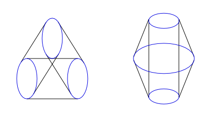
This came from the HDDB wiki for Cyltrianglinder
Please do not reupload wiki images as attachments; that wastes disk space. Just use the [img] tag to link directly to the wiki image. ~Keiji
In the second picture, it can also be a big cylinder connecting to a small circle inside. This is analogous to being 2-D and viewing a hollow triangle through a clear line-panel: O:::o:::O , and embed a circle into every point of this exact perspective. Similar to the cube inside a cube of the geochoron ( tesseract ). When the light clicks on, it's a beautiful thing!
-Philip
It is by will alone, I set my donuts in motion
- ICN5D
- Pentonian
- Posts: 1135
- Joined: Mon Jul 28, 2008 4:25 am
- Location: the Land of Flowers
Re: Understanding the Cyltrianglinder
![]() by quickfur » Wed Dec 18, 2013 7:11 pm
by quickfur » Wed Dec 18, 2013 7:11 pm
From your description, the "cyltrianglinder" is just the circle-triangle Cartesian product, which I've independently (re)discovered some years ago:

You can take the Cartesian product of any n-gon with a circle; the general process is described here.
Another construction of this cute little 4D object is to take three 3D cylinders, join them end-to-end, and then fold them up into 4D so that the top and bottom ends meet. This produces a triangular configuration of 3 cylinders, and the remaining gap can be filled with a triangular torus (basically the result of sweeping the triangle "inside out" as you described). So there are 4 surfaces to this object: 3 cylinders, which are flat, and 1 toroidal curved surface, which wraps around the object and has a triangular cross-section.
This is just the first of a series of n-gon-circle Cartesian products, the limiting shape of which as n approaches infinity is just the duocylinder. The next member of this series, interestingly enough, is none other than the cubinder (the extrusion of a 3D cylinder aka square-circle Cartesian product aka volume traced by a 3D cube rotating in 4D around the plane that bisects one of its axes). You also get cool shapes like the hexagon-circle Cartesian product two members down the series:

All of these shapes are basically generalizations of the duoprisms, and may be thought of as the limiting shapes of m,n-duoprisms as m approaches infinity (but n remains finite). If you let both m and n approach infinity, then you get the duocylinder.
You can take the Cartesian product of any n-gon with a circle; the general process is described here.
Another construction of this cute little 4D object is to take three 3D cylinders, join them end-to-end, and then fold them up into 4D so that the top and bottom ends meet. This produces a triangular configuration of 3 cylinders, and the remaining gap can be filled with a triangular torus (basically the result of sweeping the triangle "inside out" as you described). So there are 4 surfaces to this object: 3 cylinders, which are flat, and 1 toroidal curved surface, which wraps around the object and has a triangular cross-section.
This is just the first of a series of n-gon-circle Cartesian products, the limiting shape of which as n approaches infinity is just the duocylinder. The next member of this series, interestingly enough, is none other than the cubinder (the extrusion of a 3D cylinder aka square-circle Cartesian product aka volume traced by a 3D cube rotating in 4D around the plane that bisects one of its axes). You also get cool shapes like the hexagon-circle Cartesian product two members down the series:
All of these shapes are basically generalizations of the duoprisms, and may be thought of as the limiting shapes of m,n-duoprisms as m approaches infinity (but n remains finite). If you let both m and n approach infinity, then you get the duocylinder.
- quickfur
- Pentonian
- Posts: 3025
- Joined: Thu Sep 02, 2004 11:20 pm
- Location: The Great White North
18 posts
• Page 1 of 1
Who is online
Users browsing this forum: No registered users and 43 guests