I can't get through to their website at the moment. But, from the description, this looks like it could be a nice tool for making pretty tesseract pictures.
http://freshmeat.net/projects/tesseracttrainer/?branch_id=58663&release_id=198451
Tesseract Trainer --- new software out there...
16 posts
• Page 1 of 1
Tesseract Trainer --- new software out there...
![]() by pat » Fri Jun 10, 2005 4:39 pm
by pat » Fri Jun 10, 2005 4:39 pm
- pat
- Tetronian
- Posts: 563
- Joined: Tue Dec 02, 2003 5:30 pm
- Location: Minneapolis, MN
![]() by southa » Sat Jun 11, 2005 10:52 pm
by southa » Sat Jun 11, 2005 10:52 pm
Thanks for the plug! The website should be back now as the server rebooted just after I made that listing  . Apart from the main site there are reviews on versiontracker and happypenguin too.
There are also some (tested) 4D quaternion rotation recipies in the download->documents section, with references, and public domain C++ code for them in the source tree. Also my musings about 4D projection and rendering for games, with diagrams. I'm quite pleased with that one.
Nice site by the way. I look forward to lurking round here for a while.
(Andy Southgate, Mushware Limited)
. Apart from the main site there are reviews on versiontracker and happypenguin too.
There are also some (tested) 4D quaternion rotation recipies in the download->documents section, with references, and public domain C++ code for them in the source tree. Also my musings about 4D projection and rendering for games, with diagrams. I'm quite pleased with that one.
Nice site by the way. I look forward to lurking round here for a while.
(Andy Southgate, Mushware Limited)
- southa
- Dionian
- Posts: 20
- Joined: Sat Jun 11, 2005 10:28 pm
- Location: Cambridge, UK
4D games
![]() by quickfur » Mon Jun 13, 2005 9:19 pm
by quickfur » Mon Jun 13, 2005 9:19 pm
Whoa, another person interested in writing 4D games...
Have you by any chance seen John McIntosh's 4D maze game? Granted, it's in Java and uses only lines, but you can still get a pretty good feel for 4D after you get used to the interface. It's actually highly configurable and I've actually added more interesting textures to the game (octahedral patterns for the walls). (Don't know if John has included the patch yet.)
Anyway, the tesseract trainer looks interesting... will it support hidden surface clipping? Will it support other 4D objects? It looks promising as a way of visualizing 4D objects. Cool stuff.
- quickfur
- Pentonian
- Posts: 3025
- Joined: Thu Sep 02, 2004 11:20 pm
- Location: The Great White North
![]() by southa » Wed Jun 15, 2005 12:38 pm
by southa » Wed Jun 15, 2005 12:38 pm
In TT the hypercube displayed is officially transparent, so you see the whole thing and there are no hidden faces. An opaque one would be more tricky. I've a feeling that culling (hyper)faces based on their normals isn't enough because of expanded faces, and you need some sort of depth buffering or sorting as well.
As for other shapes, I tried a spherical shell made up of points. That was an interesting one - there's a weird pudding-stirring motion as the two rotation planes interact. Right now I'm moving on to a 4D environment, i.e. more cubes, and you can move about between them. Hopefully the renderer from that can be fed back into Tesseract Trainer.
(PS Tried the maze game a while ago - didn't stick at it though. Maybe I'll take another look)
- southa
- Dionian
- Posts: 20
- Joined: Sat Jun 11, 2005 10:28 pm
- Location: Cambridge, UK
![]() by quickfur » Wed Jun 15, 2005 2:28 pm
by quickfur » Wed Jun 15, 2005 2:28 pm
southa wrote:In TT the hypercube displayed is officially transparent, so you see the whole thing and there are no hidden faces. An opaque one would be more tricky. I've a feeling that culling (hyper)faces based on their normals isn't enough because of expanded faces, and you need some sort of depth buffering or sorting as well.
Culling surfaces based on normals works for convex objects. But if you have non-convex objects, you'll have to do something more. Ditto if you have objects obscuring other objects behind them. (Note that you want to cull based on the 4D normals, not the 3D normals; the 4D view should be opaque but the 3D view must be transparent, otherwise you're losing 90% of the information you need to see what's going on.)
In any case, culling surfaces is probably mandatory, esp. in 4D. It's hard enough to see what's going on in 3D if the entire environment is transparent; it gets a lot worse in 4D (mainly because 4D->2D projection produces a lot of overlaps).
As for other shapes, I tried a spherical shell made up of points. That was an interesting one - there's a weird pudding-stirring motion as the two rotation planes interact. Right now I'm moving on to a 4D environment, i.e. more cubes, and you can move about between them. Hopefully the renderer from that can be fed back into Tesseract Trainer.
Cool.
(PS Tried the maze game a while ago - didn't stick at it though. Maybe I'll take another look)
The maze game looks a bit primitive because it uses line rendering, but it's actually very well done. It has full back-face culling (but apparently it uses a simplified algorithm that just happens to work because the maze is only made of identical cubes, and corridors are only ever 1 cube wide). I learned a lot about 4D orientation playing that game. :-)
- quickfur
- Pentonian
- Posts: 3025
- Joined: Thu Sep 02, 2004 11:20 pm
- Location: The Great White North
![]() by pat » Thu Jun 16, 2005 11:37 pm
by pat » Thu Jun 16, 2005 11:37 pm
quickfur wrote:Culling surfaces based on normals works for convex objects. But if you have non-convex objects, you'll have to do something more.
??? Assuming you're not inside the object, then... [If you're inside the object, then swap "in front of" and "behind" in the following.]
For any given facet, it's on a hyperplane. Either you're in front of that hyperplane or you're behind it. If you're behind it, then your view of the objects in that hyperplane will be obscured by some other facet of the object.
Or, am I missing something?
Put another way... a light in a 4-D universe will not light up any part of the interior of a 4-D object, even if the object is non-convex.
- pat
- Tetronian
- Posts: 563
- Joined: Tue Dec 02, 2003 5:30 pm
- Location: Minneapolis, MN
![]() by quickfur » Thu Jun 16, 2005 11:46 pm
by quickfur » Thu Jun 16, 2005 11:46 pm
pat wrote:quickfur wrote:Culling surfaces based on normals works for convex objects. But if you have non-convex objects, you'll have to do something more.
??? Assuming you're not inside the object, then... [If you're inside the object, then swap "in front of" and "behind" in the following.]
For any given facet, it's on a hyperplane. Either you're in front of that hyperplane or you're behind it. If you're behind it, then your view of the objects in that hyperplane will be obscured by some other facet of the object.
[...]
Right, you still remove facets that are facing away from you. However, that is not enough: the faces that aren't culled might be (partially) obscuring each other, so you have to do 3D clipping of the projected volumes in order to get the right image. That's what I meant by "do something more". This doesn't happen with convex objects, but it does happen with non-convex objects and with multi-object scenes where objects partially obscure each other.
- quickfur
- Pentonian
- Posts: 3025
- Joined: Thu Sep 02, 2004 11:20 pm
- Location: The Great White North
![]() by pat » Fri Jun 17, 2005 2:18 am
by pat » Fri Jun 17, 2005 2:18 am
Oh, sure.... I guess I didn't read enough above. I was thinking you were talking about back-face(t) culling. Occlusion culling is much thornier.
One possible way would be to extend the concept of z-buffering into z-w-buffering. For the discussion below, assume orthographic projection. You can do perspective projection with very little alteration... it's just easier to describe orthographically.
With z-buffering, you keep an extra number for each pixel in your output image. This number keeps track of the closest thing you've hit so far at that pixel. That is, for each (x,y) you keep track of the nearest (z). If your next contact with (x,y) is closer, you update the (z) and the color of the (x,y) pixel. If your next contact with (x,y) is further, you ignore that contact. So, when you're rendering a polygon, you render it based on stepping through the screen-buffer (the (x,y)s) and knowing your (z) at each point.
For z-w buffering, things are a bit trickier. For each (x,y), you have to worry about how the facet you're rendering intersects with the plane parallel to the z-w plane and containing (x,y). This can get kinda tricky. Suppose you're rendering a hypercube. Each facet is a cube. A cube can intersect a plane as a 0-, 1-, 3-, 4-, 5-, 6-, 7-, or 8-gon. For each (x,y), you're going to have to keep track of the union of all of these polygons.
Let me try a diagram. Suppose there are two facets, both of which intersect a particular plane as a pentagon (5-gon).
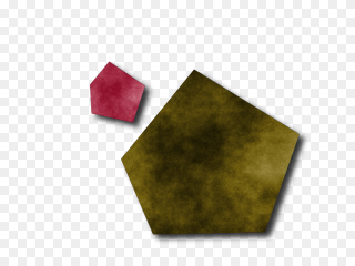
There are a few ways to go from here. For example, let's step back and pretend these were 3-d facets intersecting a 3-d scene and we're only concerned with one scanline of the image. This picture will then represent the intersection of our objects with the plane parallel to the x-z plane and containing our y. So, x varies from left-to-right. z varies from top-to-bottom. y remains constant throughout. We can recover z-buffering by only considering the colors of the highlighted pixels:
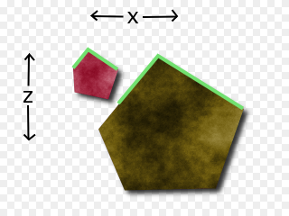
For our case, however, it's trickier. For us, w varies from left-to-right. z varies from top-to-bottom. x and y both remain constant throughout. We have to come up with a color out of this. Clearly, we don't have to worry about the internal colors of any of the polygons. We are in the plane with the polygons. The internals of them will be obscured so long as we stay outside the polygons.
But, where can we see? Assuming that up is closer in z and left is closer in w, can we see the highlighted points?
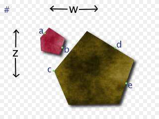
We can definitely see a. No line from from us to a is blocked in any way. The color at a should definitely be part of our color for this pixel. On the other hand, we can definitely not see b or e. Every line from us to b or e is blocked.
But, c and d are more ambiguous. And, it depends (I think) on how we are going to flatten things.
Since we're working with orthographic projection so far and we don't want to favor z over w or w over z, then either both c and d are visible or neither is. We can orthographically project to the w-axis and then sum the pixels on the w-axis *and* orthographically project to the z-axis and then sum the pixels on the z-axis, add the two together, and find the average color. This means both c and d are somewhat visible but each is only half as important as a.
Another orthographic possibility is to only figure in the points that can be projected to both axises. This doesn't make as much sense to me. I can think of no physical or geometric justification for it. But, it may reduce some visual clutter.
A third orthographic possibility would be to make two output images.... one for the projection to the w axis and one for the projection to the z axis. I like this one a lot. But, it may be too subtle an effect. For example, with the image above, one would expect both the z-color and the w-color for this object to look about the same. If, however, the red moved over to the right edge of the image, then the w-color would be significantly more red than the z-color since much of the red would then be obscured from the z-axis though not from the w-axis.
If we're doing perspective projection, the answer is easier (I think). You have to sum up over all of the colors visible from the origin (well, from the eye's orthographic projection to this plane). So, if the '#' marks the origin, then c would be visible but d would not.
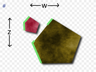
For the orthographic cases, you'd have to keep the whole border for the union of the polygons in the zw-buffer. (Actually, for the first and third orthographic cases, you can just keep the list of the projection of the union of the polygons onto the w-axis and the list of the projection of the union of the polygons onto the z-axis). For the perspective case, you'd only have to keep those borders not obscured (as seen from the origin) by other borders. You'd only have to keep these segments:
One possible way would be to extend the concept of z-buffering into z-w-buffering. For the discussion below, assume orthographic projection. You can do perspective projection with very little alteration... it's just easier to describe orthographically.
With z-buffering, you keep an extra number for each pixel in your output image. This number keeps track of the closest thing you've hit so far at that pixel. That is, for each (x,y) you keep track of the nearest (z). If your next contact with (x,y) is closer, you update the (z) and the color of the (x,y) pixel. If your next contact with (x,y) is further, you ignore that contact. So, when you're rendering a polygon, you render it based on stepping through the screen-buffer (the (x,y)s) and knowing your (z) at each point.
For z-w buffering, things are a bit trickier. For each (x,y), you have to worry about how the facet you're rendering intersects with the plane parallel to the z-w plane and containing (x,y). This can get kinda tricky. Suppose you're rendering a hypercube. Each facet is a cube. A cube can intersect a plane as a 0-, 1-, 3-, 4-, 5-, 6-, 7-, or 8-gon. For each (x,y), you're going to have to keep track of the union of all of these polygons.
Let me try a diagram. Suppose there are two facets, both of which intersect a particular plane as a pentagon (5-gon).
There are a few ways to go from here. For example, let's step back and pretend these were 3-d facets intersecting a 3-d scene and we're only concerned with one scanline of the image. This picture will then represent the intersection of our objects with the plane parallel to the x-z plane and containing our y. So, x varies from left-to-right. z varies from top-to-bottom. y remains constant throughout. We can recover z-buffering by only considering the colors of the highlighted pixels:
For our case, however, it's trickier. For us, w varies from left-to-right. z varies from top-to-bottom. x and y both remain constant throughout. We have to come up with a color out of this. Clearly, we don't have to worry about the internal colors of any of the polygons. We are in the plane with the polygons. The internals of them will be obscured so long as we stay outside the polygons.
But, where can we see? Assuming that up is closer in z and left is closer in w, can we see the highlighted points?
We can definitely see a. No line from from us to a is blocked in any way. The color at a should definitely be part of our color for this pixel. On the other hand, we can definitely not see b or e. Every line from us to b or e is blocked.
But, c and d are more ambiguous. And, it depends (I think) on how we are going to flatten things.
Since we're working with orthographic projection so far and we don't want to favor z over w or w over z, then either both c and d are visible or neither is. We can orthographically project to the w-axis and then sum the pixels on the w-axis *and* orthographically project to the z-axis and then sum the pixels on the z-axis, add the two together, and find the average color. This means both c and d are somewhat visible but each is only half as important as a.
Another orthographic possibility is to only figure in the points that can be projected to both axises. This doesn't make as much sense to me. I can think of no physical or geometric justification for it. But, it may reduce some visual clutter.
A third orthographic possibility would be to make two output images.... one for the projection to the w axis and one for the projection to the z axis. I like this one a lot. But, it may be too subtle an effect. For example, with the image above, one would expect both the z-color and the w-color for this object to look about the same. If, however, the red moved over to the right edge of the image, then the w-color would be significantly more red than the z-color since much of the red would then be obscured from the z-axis though not from the w-axis.
If we're doing perspective projection, the answer is easier (I think). You have to sum up over all of the colors visible from the origin (well, from the eye's orthographic projection to this plane). So, if the '#' marks the origin, then c would be visible but d would not.
For the orthographic cases, you'd have to keep the whole border for the union of the polygons in the zw-buffer. (Actually, for the first and third orthographic cases, you can just keep the list of the projection of the union of the polygons onto the w-axis and the list of the projection of the union of the polygons onto the z-axis). For the perspective case, you'd only have to keep those borders not obscured (as seen from the origin) by other borders. You'd only have to keep these segments:
- pat
- Tetronian
- Posts: 563
- Joined: Tue Dec 02, 2003 5:30 pm
- Location: Minneapolis, MN
![]() by quickfur » Sun Jun 19, 2005 12:42 am
by quickfur » Sun Jun 19, 2005 12:42 am
pat wrote:Oh, sure.... I guess I didn't read enough above. I was thinking you were talking about back-face(t) culling. Occlusion culling is much thornier.
Indeed. I had a discussion with John McIntosh, the guy who wrote the 4D maze game, about how to extend it to include other objects and non-cubic walls. We found that it requires clipping arbitrary 3D (non-regular) polyhedra, which is possible but complicated to implement.
One possible way would be to extend the concept of z-buffering into z-w-buffering. For the discussion below, assume orthographic projection. You can do perspective projection with very little alteration... it's just easier to describe orthographically.
[...]
Interesting approach.
My personal opinion, though, is that we should consider it as though we are only projecting from 4D -> 3D. Sure, we need to eventually get to 2D in order for the thing to be seen on the computer screen, but the point is that a full 3D image is necessary to adequately convey 4D. (Think of trying to understand 3D if your eyes had ultra-fine slits that only allowed you to see a single scanline at a time.) Culling really should only happen in the 4D->3D step.
To get the thing on screen, though, we need to project from 3D to 2D. IMHO, this second projection should be completely independent from the 4D->3D projection; it should be as though an independent entity were observing the retinal image of the 4D viewer. This second projection should be completely transparent, so that we can see the entire structure of the 3D image. We cannot do culling here, because doing so removes essential information stored in the 3D image. It's like seeing only the silhouttes of objects.
Of course, the result may be confusing, because the 3D image may be quite complex; what we can do is to do visibility or depth tests from the 3D viewpoint, and apply visual cues like shading or dotted lines, etc., to indicate 3D depth of the feature being rendered. The 3D viewpoint should be completely decoupled from the 4D viewpoint. It's essentially just a "crutch" for us poor 2D-retinal creatures to see a 3D retinal image.
Anyway, what is of real interest here is occlusion culling in the 4D->3D projection. Let's say we have two facets in the 4D scene, that projects onto two 3D polyhedra A and B. If they don't intersect, nothing further needs to be done. If they do intersect, then we have to figure out their relative distances in 4D. If A is farther than B, then the resulting image should consist of (A-B) and B, where '-' is CSG subtraction. Likewise, if B is farther than A, then the image should contain A and (B-A).
This of course assumes that A and B are disjoint in 4-space; if they are interpenetrating, then things become a lot more hairy because each point in A and B could have different depths in W, so the correct image is no longer just a simple matter of doing CSG subtractions. But we'll assume that they aren't interpenetrating for now.
If we have n facets in the scene, then we will need to perform this pair-wise clipping between all non-disjoint pairs of polyhedral images. This is roughly O(n<sup>2</sup>), unless we can come up with a smart way of sorting the facets so that we know which pairs are likely to intersect and which aren't.
Anyway, there are different approaches to how this can be done, which depends on how you represent objects in the scene. There is an interesting page that describes an algorithm using the half-space representation for polytopes: http://www.flowerfire.com/ADSODA/. Only parallel projections are considered, but I think it should be simple to adapt to perspective projections. I'm not sure about how to do the same thing using the more common vertex or (N-1)-polytope representation of objects, though. Seems in that case that we would have to compute intersections of polyhedra directly, which is not fun.
Now, we could use a 3D z-buffer (a w-buffer?), and render the 3D image like a ray-tracer would. However, this essentially "pixelates" the 3D image to a cubic array of voxels. When we then perform 3D->2D projection, we get bad aliasing effects. It's really necessary to use a mathematical, rather than pixel-based, representation in the 3D image, so that the 3D->2D projection will produce good quality.
- quickfur
- Pentonian
- Posts: 3025
- Joined: Thu Sep 02, 2004 11:20 pm
- Location: The Great White North
![]() by pat » Sun Jun 19, 2005 4:06 pm
by pat » Sun Jun 19, 2005 4:06 pm
quickfur wrote:My personal opinion, though, is that we should consider it as though we are only projecting from 4D -> 3D.
Sure... and that's what I try to convey with the multiple slices with my raytracer: the full picture

There, however, the occlusion culling happens easily because of the ray tracing.
If you were willing to take the slices approach, then you could adapt the above scheme more easily and make one slice per column. And do the occlusion culling as per row. I'll describe it more later.... family obligations now.
Last edited by pat on Sun Jun 19, 2005 7:19 pm, edited 1 time in total.
- pat
- Tetronian
- Posts: 563
- Joined: Tue Dec 02, 2003 5:30 pm
- Location: Minneapolis, MN
![]() by quickfur » Sun Jun 19, 2005 4:14 pm
by quickfur » Sun Jun 19, 2005 4:14 pm
pat wrote:quickfur wrote:My personal opinion, though, is that we should consider it as though we are only projecting from 4D -> 3D.
Sure... and that's what I try to convey with the multiple slices with my raytracer:
[...]
There, however, the occlusion culling happens easily because of the ray tracing.
Cool, is that the 120-cell or the 600-cell?
If you were willing to take the slices approach, then you could adapt the above scheme more easily and make one slice per column. And do the occlusion culling as per row. I'll describe it more later.... family obligations now.
Slicing is much easier to implement, I agree.
Thing is, I don't know about you, but I have a hard time synthesizing the original object based on a set of slices. For example, if I see a set of slices through, say, a cube, I have a hard time figuring out that it has 6 square faces and 8 vertices, unless the slices are trivial (set of identical squares). But to reconstruct an entire scene from slices, where objects are usually not at such trivial angles, is a bit beyond my pale. Maybe it's because I'm not good enough with geometry... but I still find the projection method much easier to see. Just my personal preference.
- quickfur
- Pentonian
- Posts: 3025
- Joined: Thu Sep 02, 2004 11:20 pm
- Location: The Great White North
![]() by pat » Sun Jun 19, 2005 7:18 pm
by pat » Sun Jun 19, 2005 7:18 pm
That's the 600 cell. Here's the 120-cell.

And, yes... I also find it hard to piece together the facets from the slices. But, when I do... I feel like I have a much better understanding of "where" they really are than when they all get projected down to the same space.
In particular, someone above described swirling when rotating points on a sphere. With the slices view... you can actually see the separate rotations instead of seeing it as a swirl.
- pat
- Tetronian
- Posts: 563
- Joined: Tue Dec 02, 2003 5:30 pm
- Location: Minneapolis, MN
![]() by pat » Mon Jun 20, 2005 1:03 am
by pat » Mon Jun 20, 2005 1:03 am
quickfur wrote:Anyway, there are different approaches to how this can be done, which depends on how you represent objects in the scene. There is an interesting page that describes an algorithm using the half-space representation for polytopes: http://www.flowerfire.com/ADSODA/. Only parallel projections are considered, but I think it should be simple to adapt to perspective projections. I'm not sure about how to do the same thing using the more common vertex or (N-1)-polytope representation of objects, though. Seems in that case that we would have to compute intersections of polyhedra directly, which is not fun.
It's not too hard to go from the vertex representations to the half-space representations. That's how my raytracer deals with them.
- pat
- Tetronian
- Posts: 563
- Joined: Tue Dec 02, 2003 5:30 pm
- Location: Minneapolis, MN
![]() by quickfur » Tue Jun 21, 2005 3:50 am
by quickfur » Tue Jun 21, 2005 3:50 am
pat wrote:That's the 600 cell. Here's the 120-cell.
Ahh, it makes sense. The decagonal faces are slices of dodecahedra.
And, yes... I also find it hard to piece together the facets from the slices. But, when I do... I feel like I have a much better understanding of "where" they really are than when they all get projected down to the same space.
Interesting. I find that I can "see" 4D objects much better in terms of their 3D projections, in my mind's eye. In fact, I "discovered" duoprisms (the m,n-bicycles as I called them at first) independently, by mentally manipulating the 3D projections of prismic facets embedded in 4-space.
But having said that, I find 2D projections of these 3D images in my mind woefully inadequate to help the viewer see the 4D objects. For example, I can now "see" the 24-cell in my mind as its vertex-first projection, and I can mentally rotate it along the principle planes of rotation and "see" what happens to its image. But when I look at a 2D rendering, it's very hard to discern the cells because of all the overlapping lines. It seems that these 2D projections only help me to notice things I've missed before, but the actual visualization must still happen in full 3D in my mind.
In particular, someone above described swirling when rotating points on a sphere. With the slices view... you can actually see the separate rotations instead of seeing it as a swirl.
That reminds me of an interesting (and sometimes annoying) phenomenon I stumbled across in 2D renderings of 3D projections of 4D objects. Take a look at this:

What's the first thing that comes to mind? Probably that this image looks like a 3D cube-like thing (plus some extraneous lines) rotating around the Z axis. Or the rotation of an oblique projection of the tetracube in 3D.
However, this image is actually a perspective projection of a rotating tetracube... the dotted lines aren't showing obscuring in 3D, but obscuring in 4D. The red and blue cells are actually "engulfing" each other in the 3D image (y'know, how it's shown so often, like the animation I have on my 8-cell page).
But because the equations describing the 4D rotation are analogous to those describing 3D rotations, especially from this angle, they produce an almost identical effect, and the mind is tricked into interpreting it as a 3D rotation. I had to change the viewpoint to something much closer to the plane of rotation in order to remove this illusion (see the animation on my 8-cell page, which shows the same rotation from a different 3D viewpoint).
Illusions like this are by no means rare, either. My first efforts at the duocylinder animation also looked like distorted 3D torii rotating in 3-space. It almost makes one think that these illusions, even though they are technically incorrect, perhaps have some merit in 4D visualization, since they cause your mind to interpret the image as a rotation (albeit a different one from the actual 4D rotation) rather than the turning-inside-out effect.
Of course, the bottom line is that 2D is just too low a dimension to adequately capture 4D objects. I long for the day of holographic projectors where you can see projections of 4D objects in real 3D. :-)
- quickfur
- Pentonian
- Posts: 3025
- Joined: Thu Sep 02, 2004 11:20 pm
- Location: The Great White North
![]() by pat » Tue Jun 21, 2005 4:43 am
by pat » Tue Jun 21, 2005 4:43 am
Yes... I have real trouble seeing the projection things as anything but the "turning inside out effect" which is so misleading.
Here's a duo-circle animation. The top one is radially striped in x-y. The bottom one is radially striped in z-w. The middle is both.
Here's a duo-circle animation. The top one is radially striped in x-y. The bottom one is radially striped in z-w. The middle is both.
- pat
- Tetronian
- Posts: 563
- Joined: Tue Dec 02, 2003 5:30 pm
- Location: Minneapolis, MN
![]() by quickfur » Tue Jun 21, 2005 5:12 am
by quickfur » Tue Jun 21, 2005 5:12 am
pat wrote:Yes... I have real trouble seeing the projection things as anything but the "turning inside out effect" which is so misleading.
Hmm. I actually find it helpful to get used to, 'cos once I understand what is really happening, it starts to click in my mind. I found it helpful to look at the analogous 3D->2D situation:

and compare it with the 4D->3D situation:

Once I got used to interpreting the "inside out" effect as a rotation, I can actually visualize Clifford-style rotations in 4D now (simultaneous rotation in two orthogonal planes): essentially an "inside out" rotation happening at the same time it "turns on its axis" in the 3D sense -- of course, not what is really happening, but it helps to piece the two rotations together in my mind. Then it's easier to take the next step in recognizing the two as rotations. Before I could think in terms of 3D projections of 4D this way, my mind simply shut off whenever I tried to imagine something rotating simultaneously on two orthogonal planes.
Here's a duo-circle animation. The top one is radially striped in x-y. The bottom one is radially striped in z-w. The middle is both.
Hmm, I have trouble playing this file. MPlayer crashes on it :-( Does it need a special codec?
- quickfur
- Pentonian
- Posts: 3025
- Joined: Thu Sep 02, 2004 11:20 pm
- Location: The Great White North
16 posts
• Page 1 of 1
Who is online
Users browsing this forum: No registered users and 42 guests