Some of you may have wondered (or may be wondering) how one can visualize a 3-hyperplane in 4D. In particular, visualize it well enough to be able to do intersections and stuff with it, in a visual, geometrical way that you can do with 2-planes in 3D.
It's actually not that hard. The first insight is that when we deal with planes in 3D, we do not actually visualize them as mathematical planes --- that is, we never see them in their entirety: they are objects of infinite extent, and it would take a real Cantorian to be able to grasp them in their full glory. Instead, we draw squares that represent sections of the planes that show their orientation and position. Of course, we understand these squares to extend indefinitely beyond the edges depicted on paper (or on screen); but drawing them as squares with finite extents help us correctly visualize their orientation and position in 3-space.
The second insight is that these squares that represent planes are always drawn under projection from 3-space. So they appear as trapezoids and parallelograms when we depict them on paper. The amount they are "squashed" from being a perfect square gives us an intuitive idea of the angle they make with our viewpoint.
When we depict intersections between planes, we always depict the intersections as the intersections between the squares that we use to represent the planes. In other words, the intersection between two such squares, when indefinitely extended at both ends, is equal to the intersection between the two planes being represented.
Well, how then do we visualize 3-hyperplanes in 4D? It's very simple: we just draw them as cubes! Cubes that are under projection from 4-space, of course, so that they appear as parallelopipeds and other hexahedra ("flattened" cubes). The amount they are "squashed" from being perfect cubes represent the angle they make with our 4D viewpoint. Of course, we understand that these cubes are representations of the hyperplane, a cubical section cut out to represent the entire hyperplane. And how do we represent intersections between two or more hyperplanes? We simply draw them as intersections between cubes, which in general would be squares, which, if extended indefinitely from their edges, represents the 2D intersections of 3-hyperplanes.
There, now y'all know how to visualize intersecting hyperplanes in your head. It's really just an application of dimensional analogy. :-)
P.S. This analogy, of course, can be carried further. It's easy to see that 4-hyperplanes in 5D can easily be represented by tesseracts, and intersections between 4-hyperplanes in 5D can simply be depicted as cubical intersections between two tesseracts. And you can carry this to any dimension.
Visualizing 3-hyperplanes
125 posts
• Page 1 of 5 • 1, 2, 3, 4, 5
Visualizing 3-hyperplanes
![]() by quickfur » Fri Oct 15, 2010 3:14 pm
by quickfur » Fri Oct 15, 2010 3:14 pm
- quickfur
- Pentonian
- Posts: 2955
- Joined: Thu Sep 02, 2004 11:20 pm
- Location: The Great White North
Re: Visualizing 3-hyperplanes
![]() by Prashantkrishnan » Thu Jan 16, 2014 4:04 pm
by Prashantkrishnan » Thu Jan 16, 2014 4:04 pm
I have tried these methods. These do help me to visualise projections of some rotachora like tesseract, cubinder and spherinder. As for the duocylinder and glome, we have already discussed that in another forum. But don't these methods get more complicated with an increase in the number of dimensions? Suppose we are visualising a 6-space in a 7-space with all geometric properties. We have to first visualise a cube, then visualise various frusta to completely visualise a tesseract, then some hyperfrusta(?), then a penteract and so on until we get to visualise a 6-space. Moreover, we visualise only a 3D projection of a 4D projection of a 5D projection of a 6-space. Still, this can be helpful in many ways.
Yesternight, I vaguely visualised two spheres intersecting at their circle shaped cross sectional planes in 4-space. When I tried to visualise more clearly, both the spheres came to the same realmspace. I understood the concept of chains of spheres in 5D mentioned by Mrrl in the page on knots.
Yesternight, I vaguely visualised two spheres intersecting at their circle shaped cross sectional planes in 4-space. When I tried to visualise more clearly, both the spheres came to the same realmspace. I understood the concept of chains of spheres in 5D mentioned by Mrrl in the page on knots.
People may consider as God the beings of finite higher dimensions,
though in truth, God has infinite dimensions
though in truth, God has infinite dimensions
-

Prashantkrishnan - Trionian
- Posts: 114
- Joined: Mon Jan 13, 2014 5:37 pm
- Location: Kochi, Kerala, India
Re: Visualizing 3-hyperplanes
![]() by quickfur » Thu Jan 16, 2014 7:29 pm
by quickfur » Thu Jan 16, 2014 7:29 pm
Prashantkrishnan wrote:I have tried these methods. These do help me to visualise projections of some rotachora like tesseract, cubinder and spherinder. As for the duocylinder and glome, we have already discussed that in another forum. But don't these methods get more complicated with an increase in the number of dimensions? Suppose we are visualising a 6-space in a 7-space with all geometric properties. We have to first visualise a cube, then visualise various frusta to completely visualise a tesseract, then some hyperfrusta(?), then a penteract and so on until we get to visualise a 6-space. Moreover, we visualise only a 3D projection of a 4D projection of a 5D projection of a 6-space. Still, this can be helpful in many ways.
Yesternight, I vaguely visualised two spheres intersecting at their circle shaped cross sectional planes in 4-space. When I tried to visualise more clearly, both the spheres came to the same realmspace. I understood the concept of chains of spheres in 5D mentioned by Mrrl in the page on knots.
The thing about projections is that you really want to be dealing with only n-D -> (n-1)-D projections, because any lower than (n-1)-D projections will start to lose important information. It's the equivalent of trying to visualize the tesseract (4D) with line diagrams (2D). You can do it, but it's just not quite the same as using 3D projections where you can "see" the facets directly.
Of course, since we can't see 4D directly, we have no direct way of seeing a 5D->4D projection, so we'll have to use multiple 4D->3D projections of the same 5D projection in order to be able to grasp what's going on in 5D. For example, if you indiscriminately cull hidden surfaces from the 4D image, then you're not going to be able to even see the 5D object's facets; so you need to separately project the 4D images of each facet into 3D, to see what each facet looks like, and then reconstruct the entire 4D image (with all the 4D facets in place) in order to get a glimpse into what the 5D object looks like -- from a single 5D POV.
And the effort required grows exponentially with each additional dimension: to see a 6D object, you have to first project it to 5D, so you get a 5D image which is a mosaic of various facets from 6D. But since we can't see 5D directly, we have to individually project each of the facets in the 5D mosaic into 4D (you can't jump directly to 3D here, because you'd lose information about where the facet's surtopes are). So for each of the 4D facets of the 5D facet, you have to do a projection into 3D in order to be able to reconstruct each 4D facet, then reconstruct in your mind the shape of the 5D facet. And you have to repeat this for each 5D facet, and somehow keep track of everything in your head, and then finally assemble each 5D facet in your mind into the 6D object. Now if you were dealing with a 7D object, you'd have to repeat this process for every 6D facet of the 7D object, and then assembly everything at the end into the 7D object.
As you can see, this quickly becomes impractical as the number of dimensions grows, since the number of elements in an n-dimensional polytope increases exponentially with n. This is why most people prefer to study highly-symmetrical objects: the high degree of symmetry allows you to "collapse" most of the exponential number of elements into a manageable number of equivalence classes. Outside of highly-symmetrical objects, I don't think anyone can realistically visualize objects beyond 6D or 7D or somewhere thereabouts. For sure, past 10D things become just unmanagably complex. Things also start acquiring strange, counterintuitive properties, like the n-cube having most of its volume concentrated around its vertices rather than its center, and the n-sphere's volume becoming so small relative to the n-cube it inscribes that given a high enough n, you can fit a huge number of n-spheres into the n-cube (even though in 3D you can't even fit two!).
- quickfur
- Pentonian
- Posts: 2955
- Joined: Thu Sep 02, 2004 11:20 pm
- Location: The Great White North
Re: Visualizing 3-hyperplanes
![]() by wendy » Fri Jan 17, 2014 7:58 am
by wendy » Fri Jan 17, 2014 7:58 am
Using the language of geometers to describe 3-hyperplanes etc will only get you into more trouble. They do not make the crucial distinctions necessary to do this.
Plane geometry is something you do on the ground, and Solid geometry is something you do with solids. So to make the occasional foray into four dimensions, hyper-this and hyper-that suffice. If you are really going to look at looking at four dimensions as 'solid space', you need to put a new view on things.
Things that divide are like equal signs. So eg, a line divides a hedrix, and a hedrix divides a chorix, can all be represented by a single equal sign: z=0. We feel gravity, which puts us in the space of air, where no more fall is let, gives us z=0. A fence stops things wandering across the plane, so it's of limited height, say z=0 to 1, and has a second equal sign, y=5. It's the intersection of a plane z=0, and a wall at y=5. z=0,y=5 gives a point in 2D, a line in 3D, a hedrix in 4D.
Geometers don't think like this. Instead, things have 'right angles', that is, are of fixed dimensions. So a wall as we see it is a hedrid thing, So it must be a hedrid thing for everyone. So the chorid thing needs a new name. Railway lines unite, and stay 1d in all space,
Drop the hyper-nonsense, sit down and work out whether things unite or divide, because common language is more a case of division, rather than union, and call things by the meaning of unites or divides. So a wall is not 2d, but N-1 d, and a knife edge (whose sweep divides something), is not 1D, but N-2 D. Once you get this idea, it's not too hard to get N-1 to be a plane, and grasp 3d space as a photo or map in 4D.
The dream you dream alone is only a dream
the dream we dream together is reality.
\ ( \(\LaTeX\ \) \ ) [no spaces] at https://greasyfork.org/en/users/188714-wendy-krieger
the dream we dream together is reality.
\ ( \(\LaTeX\ \) \ ) [no spaces] at https://greasyfork.org/en/users/188714-wendy-krieger
-

wendy - Pentonian
- Posts: 2014
- Joined: Tue Jan 18, 2005 12:42 pm
- Location: Brisbane, Australia
Re: Visualizing 3-hyperplanes
![]() by quickfur » Fri Jan 17, 2014 3:59 pm
by quickfur » Fri Jan 17, 2014 3:59 pm
wendy wrote:Using the language of geometers to describe 3-hyperplanes etc will only get you into more trouble. They do not make the crucial distinctions necessary to do this.
Plane geometry is something you do on the ground, and Solid geometry is something you do with solids. So to make the occasional foray into four dimensions, hyper-this and hyper-that suffice. If you are really going to look at looking at four dimensions as 'solid space', you need to put a new view on things.
Things that divide are like equal signs. So eg, a line divides a hedrix, and a hedrix divides a chorix, can all be represented by a single equal sign: z=0. We feel gravity, which puts us in the space of air, where no more fall is let, gives us z=0. A fence stops things wandering across the plane, so it's of limited height, say z=0 to 1, and has a second equal sign, y=5. It's the intersection of a plane z=0, and a wall at y=5. z=0,y=5 gives a point in 2D, a line in 3D, a hedrix in 4D.
Geometers don't think like this. Instead, things have 'right angles', that is, are of fixed dimensions. So a wall as we see it is a hedrid thing, So it must be a hedrid thing for everyone. So the chorid thing needs a new name. Railway lines unite, and stay 1d in all space,
Drop the hyper-nonsense, sit down and work out whether things unite or divide, because common language is more a case of division, rather than union, and call things by the meaning of unites or divides. So a wall is not 2d, but N-1 d, and a knife edge (whose sweep divides something), is not 1D, but N-2 D. Once you get this idea, it's not too hard to get N-1 to be a plane, and grasp 3d space as a photo or map in 4D.
I agree with all this, but I don't see how it relates to the discussion at hand?
- quickfur
- Pentonian
- Posts: 2955
- Joined: Thu Sep 02, 2004 11:20 pm
- Location: The Great White North
Re: Visualizing 3-hyperplanes
![]() by ICN5D » Mon Jan 20, 2014 6:32 am
by ICN5D » Mon Jan 20, 2014 6:32 am
When I try to visualize a new, higher dimension, I "flatten" down the existing one into a 2-D sheet, like a piece of paper. The next higher dimension becomes up and down, above and below the n-plane. Since a higher dimension is a new, perpendicular direction, that branches away from all others, this little trick works well. When I visualize a linear operation of a 4-d shape, into 5-d, I am flattening down the 4-d shape, into a 2-d drawing of it, and applying the motion in a more familiar way. Each shape essentially has pairs of side panels, or single, toric ones resting on the axis (for all of the regular polytopes). The shape can be rotated around and viewed through these different side panels, giving us a near-side, far-side pairing along with the intermediate connecting sides within.
When I visualize the construction of a cylconinder, (II)'(II), or |O>|O, I start with the line, | . The next motion is the spin, O , in which we spin the line into 2-D, to make a circle, |O, or (II) . The next motion is the taper, where we shrink the circle to a point along Z, into 3-D, to make a cone, |O>, or (II)' . When the cone extrudes into 4-D, all of the side panels are also undergoing an extrusion. The circle becomes a cylinder, the point at the top becomes a line, and the line torus connecting them becomes a square torus. This makes the coninder, |O>|, or (II)'I, which has two viewing angles: the cone to cone perspective, and the cylinder to line perspective. The cylinder to line is what one sees when rotating the prism around and looks through the cylinder side. This also means that not only does a cone-prism have a parallel pairing of sides, but also a triangular pairing, where a complex shape scales down to a lesser. Similar to a triangle prism having both a triangle to triangle, and a square to line perspective. The final operation is another spin, where upon flattening the cone-prism into a 2-D drawing, we can spin like a square. The two cone ends are traced around in a circle, and joined together into a cone torus, the cylinder and line become spun into a duocylinder and circle, and the square torus becomes spun into a cylinder torus.
This allows us a unique way to see how a duocylinder connects to a circle, along 5-D. That is ultimately what a cylconinder is, a cone-like shape with a complex 4-D base scaling down to a 2-D "vertex", which also happens to be the subshape of the two torii on the base. The duocylinder has two circle torii on its surface, and each one connects to the circle-vertex in a different way. Consider how the circle-vertex is 2-D, and "embedded" into the XY plane of 2-D. This means that on the surface of the duocylinder-base, the circle torus that lies flat on the xy plane will be seeing the circle from edge on, and will connect to only the surface of the circle, which is a dot torus, or glomolatrix. When a circle torus scales down to a dot torus, the same process is at work when a circle tapers to a dot, they make a cone. This becomes one of the connecting torii between the base and vertex. The other circle torus side panel, that rests flat on the ZW plane, will view the circle from a higher perspective, from above and below, and see the entire circle. In the same case as a circle connecting to a circle, a cylinder torus is formed, as the second connecting side.
The funny thing about 5-D, is that is some shapes are very similar to those in 3-D. It seems like 5-D is a little easier to visualize than 4-D, with some of the shapes. They are all of the ones that end with a |O, or (II), the operations of a circle, which can also be the cartesian product with a circle. I like to call these shapes the "cylindrified" rotopes, in that they are all complex cylinder-like shapes, analogous to our 3-D cylinder ( which is a simple line-cylinder in relation to the others ). So, in essence, the cylhemoctahedrinder, ||>|O or II'(II) can be thought of, and visualized as a cylindrified square pyramid. The two viewing angles of a square pyramid are: square to point, and triangle to line. The same perspectives apply to the cylhemoctahedrinder: a cubinder to circle, and a cyltrianglinder to cylinder. We can derive the higher viewing angles by adding the circle-product to lower. Same goes for a cyltetrahedrinder, |>>|O or I''(II): similar to the triangle to point perspective of a tetrahedron, the |>>|O has a cyltrianglinder tapering down to a circle, as the vertex. It is interesting to note how the contrianglinder, |O>[|>] or (II)'(I'), has a cyltrianglinder tapering down to a triangle, along 5-D. It does so with its triangle torus, connecting to the triangle-vetrex, another torus to subshape tapering.
And likewise with anything in 6-D or 7-D, I keep flattening down, compressing the current spaces into a flat n-plane, and interpret the familiar up and down direction as that of n+1, above and below, in a new perpendicular way. Extruding is still extruding, tapering is still tapering, and spinning is still applied by rotating certain side-pairs together, to make a torus.
Construction sequence for the cylconinder |O>|O :
|O : circle
| --y--> Ox == |O
---------------------------------
[ *-2 --> (O) ] == [ *(O) ]xy
|O> : cone
|O --z--> * == |O>
--------------------------------
[ *(O) --> * ] == [ |(O) ]xy
-------------------[ |O-* ]z
|O>| : coninder
|O> ---w--> |O> == |O>|
---------------------------------------
[ |(O) ---> |(O) ] == [ ||(O) ]xy
[ |O-* ---> |O-* ] == [ |O|-| ]z
-------------------------[ |O>-2 ]w
|O>|O : cylconinder
|O>| ---v--> Ow == |O>|O
-----------------------------------------
[ ||(O) ----> O ] == [ ||O(O) ]xy
[ |O|-| ----> O ] == [ |O|O-|O ]z
[ |O>-2 --> (O) ] == [ |O>(O) ]wv
It is by will alone, I set my donuts in motion
- ICN5D
- Pentonian
- Posts: 1135
- Joined: Mon Jul 28, 2008 4:25 am
- Location: the Land of Flowers
Re: Visualizing 3-hyperplanes
![]() by wendy » Tue Jan 21, 2014 11:09 am
by wendy » Tue Jan 21, 2014 11:09 am
The gist of my earlier message is that you have to unload a lot of baggage before you can start seeing 4d in its true light.
For example, it's all right to imagine the chorix as a plane, and look at the thing as a three-dimensional thing. This is how i started, and what ICN5D is saying. But you have to keep in mind that you are not going to fall through a plane because it's "1 equal sign", not because you're seeing something you don't fall through in 3d (ie a 2-space).
You can't like Rupyard Kipling's "Riki Tiki Tuva", just 'run out-side and have a look'. You have to make the maths up in your own mind. What i was saying is you really have to prepare the words in the mind and unload the baggage. Think things through.
A 2-d thing in four dimensions is not a 'surface'. You can no more cover your 4d bed with a hedrix than covering your 3d bed with a peice of string. Of course you can put criss-caps in a hedrix in 4d, and all sorts of other topological wonders. But it's like knotting a peice of string (latrix) in 3d. A surface _covers_ in any space. A hedrix does not cover in any space higher than 3d.
Instead of calling it a 'hyper-plane', call it a 3-space, or a chorix, or something. Make it real. When you get up to five dimensions, your hyper-plane as a slit of 4d is the sort of things you put on monkey-bars so you can swing around them. Hyper-plane indeed! If you think of it as a chorix in a petix, or a marginix, or something that suggests '2 equal signs', then you are in the right place for knife-edges and monkey-bars so forth. If you think of it as 3-right angles, you're not in the right place to jump to the next dimension.
The dream you dream alone is only a dream
the dream we dream together is reality.
\ ( \(\LaTeX\ \) \ ) [no spaces] at https://greasyfork.org/en/users/188714-wendy-krieger
the dream we dream together is reality.
\ ( \(\LaTeX\ \) \ ) [no spaces] at https://greasyfork.org/en/users/188714-wendy-krieger
-
wendy - Pentonian
- Posts: 2014
- Joined: Tue Jan 18, 2005 12:42 pm
- Location: Brisbane, Australia
Re: Visualizing 3-hyperplanes
![]() by ac2000 » Wed Jan 22, 2014 2:51 am
by ac2000 » Wed Jan 22, 2014 2:51 am
Sorry, when I'm asking a question about a four year old post. But as there where some recent posts on this thread this year, it should be OK, I guess.
Quickfur: I did not understand that bit from your first post.
Why would the intersection between cubes be squares?
When I imagine two intersecting cuboids the intersection would look to me like a parallelepiped (or if the cubes intersect each other in a rectangular fashion more like a rectangular cuboid).
quickfur wrote: And how do we represent intersections between two or more hyperplanes? We simply draw them as intersections between cubes, which in general would be squares,
Quickfur: I did not understand that bit from your first post.
Why would the intersection between cubes be squares?
When I imagine two intersecting cuboids the intersection would look to me like a parallelepiped (or if the cubes intersect each other in a rectangular fashion more like a rectangular cuboid).
- ac2000
- Dionian
- Posts: 28
- Joined: Sat Mar 12, 2011 7:15 am
- Location: Berlin, Germany
Re: Visualizing 3-hyperplanes
![]() by quickfur » Wed Jan 22, 2014 5:50 am
by quickfur » Wed Jan 22, 2014 5:50 am
ac2000 wrote:Sorry, when I'm asking a question about a four year old post. But as there where some recent posts on this thread this year, it should be OK, I guess.quickfur wrote: And how do we represent intersections between two or more hyperplanes? We simply draw them as intersections between cubes, which in general would be squares,
Quickfur: I did not understand that bit from your first post.
Why would the intersection between cubes be squares?
When I imagine two intersecting cuboids the intersection would look to me like a parallelepiped (or if the cubes intersect each other in a rectangular fashion more like a rectangular cuboid).
Intersecting two cuboids in 3D indeed gives parallelopipeds. But we're talking about intersecting cubes in 4D. To illustrate what I mean, look at this diagram of two intersecting 3D planes:
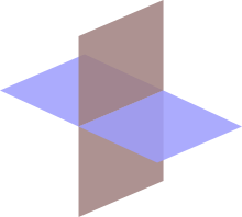
Note that the intersection here is a line (segment), but only when we interpret the two rectangles in a 3D way! If you interpret them in a 2D manner, then they would be parallelograms, and their intersection is certainly bigger than the line segment depicted above.
Similarly, when we draw intersecting cubes in 4D (which are actually parallelopipeds, not regular cubes), we draw them with a rectangular intersection because they are to be interpreted in a 4D manner, not as intersecting 3D volumes.
- quickfur
- Pentonian
- Posts: 2955
- Joined: Thu Sep 02, 2004 11:20 pm
- Location: The Great White North
Re: Visualizing 3-hyperplanes
![]() by ac2000 » Wed Jan 22, 2014 6:44 am
by ac2000 » Wed Jan 22, 2014 6:44 am
Thank you, quickfur for your explanation. 
It's a bit clearer to me now. I'm not sure if I have fully understood it, but I have to think about it first for a while ...
It's a bit clearer to me now. I'm not sure if I have fully understood it, but I have to think about it first for a while ...
- ac2000
- Dionian
- Posts: 28
- Joined: Sat Mar 12, 2011 7:15 am
- Location: Berlin, Germany
Re: Visualizing 3-hyperplanes
![]() by ICN5D » Wed Jan 22, 2014 8:02 am
by ICN5D » Wed Jan 22, 2014 8:02 am
Visualizing is sort of a matter of "feel". Now, if you are more the type of person who is better at written or verbal driving directions, seeing in 4-D will be rather tough. But, if you are far more visual, and suck at verbal directions, and need to actually see the shape of the roads on a map (like me), then visualizing what cannot be physically seen will come more naturally.
It's best to start off with something more familiar, like 2-D to 3-D transitions, then make some generalizations. These can then be transferred over when comparing 3-D to 4-D. There are many ways to make higher shapes from lower ones. There are linear operations, cartesian products, manifold embedding ( same as products ), perspective products ( an algorithm I've developed ), truncation, etc. I started with the linear operations of a line, to make some very basic 2-D shapes. You can think of a linear operation as a motion, or transformation that you did to a starting shape. To start off, we have the extrude, taper, and spin. Applying these motions to a line will trace out, and create, 3 new 2-D shapes.
Extrusions make prisms, where we maintain the starting shape, and literally "drag" it across a new higher direction. Prisms have at least one identical pairing of side panels, intersected by an axis. Extruding a line will make a square, pretty straightforward. We have an identical pairing of lines, where the other two lines emerge as a formality, due to the nature of the surface of a line, as being two points.
Tapering will make pyramids and cones, where we shrink the starting shape down to a point, while dragging across N+1. Tapering a line will make a triangle.
Spinning a shape around into the next higher dimension will create spheres ( generally speaking ), and cylinders ( generalized cylinders ). The spin of a line will trace out the shape of a disk, or circle.
By using these three 2-D shapes as starting base-shapes, the same three linear operations will create 9 shapes in 3-D. However, there will be two of these that end up being the same, making for 7 unique 3-D shapes. Note how this is a very simplified way of creating new shapes. There are infinite ways to manipulate and modify a shape to create something new. But, for simplicity, let's stick with these three operations first. Since we are talking about linear operations, I am inclined to use a notation system that I have developed. There is another one on this forum that has been in place for a long time, and I respect that. However, when comparing shapes and linear processes, I find my notation just slightly more intuitive, with my full respect for the original notation. In paying homage, I will include both.
I use the " | " symbol to denote a line. It's an easy one, because it looks like a line . This also happens to be the symbol for " extrude ". So, || would be the " formula" for a square: the extrusion of a line.
The " > " symbol stands for the taper operation. It also intuitively suggests " shrinking to a point ". So, |> would be a triangle, the taper of a line.
The " O " symbol is the spin. Much like the " | " , " O " also sort of looks like rotating something around, into N+1 dimensions. This would make |O the circle, spin of a line.
To recap, we have:
| - extrude
> - taper
O - spin
| - line
|| - square, line-prism
|> - triangle, line-pyramid
|O - circle, spin of line
Now we have three really awesome 2-D starting shapes to make 3-D shapes. By simply applying these motions to the elementary 3, we will derive the 9 new ones.
|| - square
||| - cube, square-prism
||> - pyramid, square-pyramid
||O - cylinder, spin of square
|> - triangle
|>| - triangle-prism
|>> - tetrahedron, triangle-pyramid
|>O - cone, spin of triangle
|O - circle
|O| - cylinder, circle-prism
|O> - cone, circle-pyramid
|OO - sphere, spin of circle
As mentioned before, the two repeating shapes we get are the cone and cylinder. Both can be made by flipping the spin around:
Cylinder, |O| and ||O
Cone, |O> and |>O.
This cool little reversible nature of the spin carries itself into 4-D and beyond. Many more shapes can be created twice or more through this method, with linear operations.
Okay, well, I just had to go out and celebrate my 31st birthday, which is today, and enjoy myself while I'm still young enough to be able to enjoy myself, right in the middle of writing this post. So, please excuse me of any possible changes to word choice and/or grammar, from here on out. Having said that, let's continue....
Now, in order to "visualize" a 4-D object, it could be just as simple as performing another one of these linear operations, to any one of the 3-D shapes we just created. A simple extrude, perhaps, to a 3-D object, will create a prism of this shape. A new 4-D prism, where the starting shape has been dragged across 4-D, and traced out a higher shape, with end caps made of the starting shape. This is when we see a smaller shape inside a larger one, where the two are the near-side, far-side pair. The tesseract can be viewed as a cube inside a cube, where the smaller cube is really the same size, but further away, in the 4th dimension. A cubinder can be viewed as a cylinder inside a cylinder, and coninder is a cone inside a cone, etc. That's what prisms are, connecting two identical shapes together, across N+1. ( N+1 is a shortcut way of saying " next higher dimension" )
The important thing to remember, when trying to visualize the 4th, is that once you think you have it, another new vision will come to you, another new way of seeing it, and you will see an even grander depth to what it really is. The 4th spatial dimension is truly "somewhere else", in a crazy freaking direction that you never thought about before. Something that has been hiding there, in plain sight, all this time. Somewhere that you cannot feel or touch, or even see in, but you know it's there, because it's mathematically possible. Same as any 3-D shape. They exist, a sphere or cube exists, because they are mathematically possible. Same as any 4-D, 5-D, 6-D, etc, shape. I guess you just have to have enough faith, when things get difficult, ( as was the tiger for me), that these shapes are indeed real, and you just have yet to grasp it. If I were to bend my arm into the 4th, up to my elbow, my arm will have disappeared to the elbow. That is where the 4th dimension is, a completely new and different direction, "out there" and off of this 3-plane. Freaky, isn't it?
Here is a quicklist of a few of the 4-D shapes that can be created, by the methods discussed:
PRISMS of 3-D SHAPES:
|||| - tesseract, cube-prism
||>| - square pyramid-prism
||O| - cubinder, cylinder-prism
|>|| - triangle diprism
|>>| - tetrahedrinder, tetrahedron-prism
|>O| - coninder, cone-prism
|O|| - cubinder*
|O>| - coninder*
|OO| - spherinder, sphere-prism
PYRAMIDS OF 3-D SHAPES:
|||> - hemdodecachoron, cube-pyramid
||>> - dipyramid, square pyramid pyramid
||O> - cylindrone, cylinder-pyramid
|>|> - triangle prism pyramid
|>>> - pentachoron, tetrahedron pyramid
|>O> - dicone, cone pyramid
|O|> - cylindrone*
|O>> - dicone*
|OO> - sphone, sphere pyramid
SPINS OF 3-D SHAPES:
|||O - cubinder*
||>O - cylindrone*
||OO - duocylinder, spin of cylinder
|>|O - cyltrianglinder, spin of triangle prism
|>>O - dicone, spin of tetrahedron
|>OO - sphone*
|O|O - duocylinder*
|O>O - sphone*
|OOO - glome, spin of sphere
* denotes the shapes that have been repeated
So, here we have created 17 unique 4-D shapes with only three motions in sequence. The spins are more abstract than the taper or extrude. Spinning a shape into N+1, the next highest dimension, will turn some side panel pairs into a single torus, and rotate the rest normally. This torus is the new rolling surface, a staple of any N-cylinder, or shape that has been spun around. For a shape of any dimension, only one pair will become a torus during the spin. The rest become N-cylinders ( any shape that is a cartesian product with a circle).
When conceiving a 4-D pyramid-type shape, remember that the slices are the base-shape shrinking to a point. A cube-pyramid, |||>, sliced from bottom to top, will be a cube that shrinks to a point, as we move up along W ( the axis of 4-D ). A Triangle prism pyramid, |>|>, sliced bottom to top, will be a triangle prism shrinking to a point, etc. Any prism, sliced a certain way, will be the starting shape of unchanging size, while moving along W.
Slicing a spun shape is a little different. The rolling surface makes a different cross section than the rest. Such is the case of a cyltrianglinder, |>|O, the spin of the triangle prism. On the surface of a triangle prism, we have two triangles ( the identical, prism pair ), and three squares, made from connecting the three lines of both triangles. The spin will turn the two triangles into a single torus, and the three squares into three cylinders, bounded by the triangle-torus. Now we have this 4-D, cylinder-like shape, with three flat sides and a single, continuous rolling surface. When this rolling surface is placed flat on our 3-plane, it will take up the space of a triangle. Much like how our cylinder ( a line-cylinder, by analogy ), will take up the space of a line, when placed flat on its rolling side. Slicing the cyltrianglinder lengthwise, along its rolling surface, will start as a triangle, expand into a triangle-prism, then shrink back into a triangle. Slicing from the flat, cylinder side, we will have a cylinder that scales down to a circle. The cyltrianglinder can also be created by the cartesian product of a triangle and a circle, represented by |>[|O], or |O[|>], in the notation I am using.
This does not describe any of the torii, or shapes with holes, as that can get into another page-long post, that I am capable of, especially at 3:00 in the morning, with the next day off. You are better off studying the awesome post by Marek14, on page 6 in the thread " The Tiger Explained", in the toratope section. There you will find a very deep dive into some of the craziest things you never thought about, like the tiger. It is a cartesian product of two manifolds, hollow circles, that then had a circle embedded into the wireframe, to create the duotorus. It's a far more amazing, and crazier shape that you'd be best not to try out first, but all of the rest of 4-D beforehand.
A translation of the other notation that you will find on this forum:
|| - II
|> - I'
|O - (II)
--------------
||| - III
||> - II'
|>| - I'I
|>> - I''
|O> - (II)'
|O| - (II)I
|OO - (III)
----------------
|||| - IIII
||>| - II'I
||O| - (II)II
|>|| - I'II
|>>| - I''I
|O>| - (II)'I
|OO| - (III)I
|||> - III'
||>> - II''
||O> - (II)I'
|>|> - I'I'
|>>> - I'''
|>O> - (II)''
|OO> - (III)'
||OO - (II)(II)
|>|O - I'(II)
|OOO - (IIII)
Hope that helps any, I may elaborate on this a little more, in the future.
-Philip
It's best to start off with something more familiar, like 2-D to 3-D transitions, then make some generalizations. These can then be transferred over when comparing 3-D to 4-D. There are many ways to make higher shapes from lower ones. There are linear operations, cartesian products, manifold embedding ( same as products ), perspective products ( an algorithm I've developed ), truncation, etc. I started with the linear operations of a line, to make some very basic 2-D shapes. You can think of a linear operation as a motion, or transformation that you did to a starting shape. To start off, we have the extrude, taper, and spin. Applying these motions to a line will trace out, and create, 3 new 2-D shapes.
Extrusions make prisms, where we maintain the starting shape, and literally "drag" it across a new higher direction. Prisms have at least one identical pairing of side panels, intersected by an axis. Extruding a line will make a square, pretty straightforward. We have an identical pairing of lines, where the other two lines emerge as a formality, due to the nature of the surface of a line, as being two points.
Tapering will make pyramids and cones, where we shrink the starting shape down to a point, while dragging across N+1. Tapering a line will make a triangle.
Spinning a shape around into the next higher dimension will create spheres ( generally speaking ), and cylinders ( generalized cylinders ). The spin of a line will trace out the shape of a disk, or circle.
By using these three 2-D shapes as starting base-shapes, the same three linear operations will create 9 shapes in 3-D. However, there will be two of these that end up being the same, making for 7 unique 3-D shapes. Note how this is a very simplified way of creating new shapes. There are infinite ways to manipulate and modify a shape to create something new. But, for simplicity, let's stick with these three operations first. Since we are talking about linear operations, I am inclined to use a notation system that I have developed. There is another one on this forum that has been in place for a long time, and I respect that. However, when comparing shapes and linear processes, I find my notation just slightly more intuitive, with my full respect for the original notation. In paying homage, I will include both.
I use the " | " symbol to denote a line. It's an easy one, because it looks like a line
. This also happens to be the symbol for " extrude ". So, || would be the " formula" for a square: the extrusion of a line.The " > " symbol stands for the taper operation. It also intuitively suggests " shrinking to a point ". So, |> would be a triangle, the taper of a line.
The " O " symbol is the spin. Much like the " | " , " O " also sort of looks like rotating something around, into N+1 dimensions. This would make |O the circle, spin of a line.
To recap, we have:
| - extrude
> - taper
O - spin
| - line
|| - square, line-prism
|> - triangle, line-pyramid
|O - circle, spin of line
Now we have three really awesome 2-D starting shapes to make 3-D shapes. By simply applying these motions to the elementary 3, we will derive the 9 new ones.
|| - square
||| - cube, square-prism
||> - pyramid, square-pyramid
||O - cylinder, spin of square
|> - triangle
|>| - triangle-prism
|>> - tetrahedron, triangle-pyramid
|>O - cone, spin of triangle
|O - circle
|O| - cylinder, circle-prism
|O> - cone, circle-pyramid
|OO - sphere, spin of circle
As mentioned before, the two repeating shapes we get are the cone and cylinder. Both can be made by flipping the spin around:
Cylinder, |O| and ||O
Cone, |O> and |>O.
This cool little reversible nature of the spin carries itself into 4-D and beyond. Many more shapes can be created twice or more through this method, with linear operations.
Okay, well, I just had to go out and celebrate my 31st birthday, which is today, and enjoy myself while I'm still young enough to be able to enjoy myself, right in the middle of writing this post. So, please excuse me of any possible changes to word choice and/or grammar, from here on out. Having said that, let's continue....
Now, in order to "visualize" a 4-D object, it could be just as simple as performing another one of these linear operations, to any one of the 3-D shapes we just created. A simple extrude, perhaps, to a 3-D object, will create a prism of this shape. A new 4-D prism, where the starting shape has been dragged across 4-D, and traced out a higher shape, with end caps made of the starting shape. This is when we see a smaller shape inside a larger one, where the two are the near-side, far-side pair. The tesseract can be viewed as a cube inside a cube, where the smaller cube is really the same size, but further away, in the 4th dimension. A cubinder can be viewed as a cylinder inside a cylinder, and coninder is a cone inside a cone, etc. That's what prisms are, connecting two identical shapes together, across N+1. ( N+1 is a shortcut way of saying " next higher dimension" )
The important thing to remember, when trying to visualize the 4th, is that once you think you have it, another new vision will come to you, another new way of seeing it, and you will see an even grander depth to what it really is. The 4th spatial dimension is truly "somewhere else", in a crazy freaking direction that you never thought about before. Something that has been hiding there, in plain sight, all this time. Somewhere that you cannot feel or touch, or even see in, but you know it's there, because it's mathematically possible. Same as any 3-D shape. They exist, a sphere or cube exists, because they are mathematically possible. Same as any 4-D, 5-D, 6-D, etc, shape. I guess you just have to have enough faith, when things get difficult, ( as was the tiger for me), that these shapes are indeed real, and you just have yet to grasp it. If I were to bend my arm into the 4th, up to my elbow, my arm will have disappeared to the elbow. That is where the 4th dimension is, a completely new and different direction, "out there" and off of this 3-plane. Freaky, isn't it?
Here is a quicklist of a few of the 4-D shapes that can be created, by the methods discussed:
PRISMS of 3-D SHAPES:
|||| - tesseract, cube-prism
||>| - square pyramid-prism
||O| - cubinder, cylinder-prism
|>|| - triangle diprism
|>>| - tetrahedrinder, tetrahedron-prism
|>O| - coninder, cone-prism
|O|| - cubinder*
|O>| - coninder*
|OO| - spherinder, sphere-prism
PYRAMIDS OF 3-D SHAPES:
|||> - hemdodecachoron, cube-pyramid
||>> - dipyramid, square pyramid pyramid
||O> - cylindrone, cylinder-pyramid
|>|> - triangle prism pyramid
|>>> - pentachoron, tetrahedron pyramid
|>O> - dicone, cone pyramid
|O|> - cylindrone*
|O>> - dicone*
|OO> - sphone, sphere pyramid
SPINS OF 3-D SHAPES:
|||O - cubinder*
||>O - cylindrone*
||OO - duocylinder, spin of cylinder
|>|O - cyltrianglinder, spin of triangle prism
|>>O - dicone, spin of tetrahedron
|>OO - sphone*
|O|O - duocylinder*
|O>O - sphone*
|OOO - glome, spin of sphere
* denotes the shapes that have been repeated
So, here we have created 17 unique 4-D shapes with only three motions in sequence. The spins are more abstract than the taper or extrude. Spinning a shape into N+1, the next highest dimension, will turn some side panel pairs into a single torus, and rotate the rest normally. This torus is the new rolling surface, a staple of any N-cylinder, or shape that has been spun around. For a shape of any dimension, only one pair will become a torus during the spin. The rest become N-cylinders ( any shape that is a cartesian product with a circle).
When conceiving a 4-D pyramid-type shape, remember that the slices are the base-shape shrinking to a point. A cube-pyramid, |||>, sliced from bottom to top, will be a cube that shrinks to a point, as we move up along W ( the axis of 4-D ). A Triangle prism pyramid, |>|>, sliced bottom to top, will be a triangle prism shrinking to a point, etc. Any prism, sliced a certain way, will be the starting shape of unchanging size, while moving along W.
Slicing a spun shape is a little different. The rolling surface makes a different cross section than the rest. Such is the case of a cyltrianglinder, |>|O, the spin of the triangle prism. On the surface of a triangle prism, we have two triangles ( the identical, prism pair ), and three squares, made from connecting the three lines of both triangles. The spin will turn the two triangles into a single torus, and the three squares into three cylinders, bounded by the triangle-torus. Now we have this 4-D, cylinder-like shape, with three flat sides and a single, continuous rolling surface. When this rolling surface is placed flat on our 3-plane, it will take up the space of a triangle. Much like how our cylinder ( a line-cylinder, by analogy ), will take up the space of a line, when placed flat on its rolling side. Slicing the cyltrianglinder lengthwise, along its rolling surface, will start as a triangle, expand into a triangle-prism, then shrink back into a triangle. Slicing from the flat, cylinder side, we will have a cylinder that scales down to a circle. The cyltrianglinder can also be created by the cartesian product of a triangle and a circle, represented by |>[|O], or |O[|>], in the notation I am using.
This does not describe any of the torii, or shapes with holes, as that can get into another page-long post, that I am capable of, especially at 3:00 in the morning, with the next day off. You are better off studying the awesome post by Marek14, on page 6 in the thread " The Tiger Explained", in the toratope section. There you will find a very deep dive into some of the craziest things you never thought about, like the tiger. It is a cartesian product of two manifolds, hollow circles, that then had a circle embedded into the wireframe, to create the duotorus. It's a far more amazing, and crazier shape that you'd be best not to try out first, but all of the rest of 4-D beforehand.
A translation of the other notation that you will find on this forum:
|| - II
|> - I'
|O - (II)
--------------
||| - III
||> - II'
|>| - I'I
|>> - I''
|O> - (II)'
|O| - (II)I
|OO - (III)
----------------
|||| - IIII
||>| - II'I
||O| - (II)II
|>|| - I'II
|>>| - I''I
|O>| - (II)'I
|OO| - (III)I
|||> - III'
||>> - II''
||O> - (II)I'
|>|> - I'I'
|>>> - I'''
|>O> - (II)''
|OO> - (III)'
||OO - (II)(II)
|>|O - I'(II)
|OOO - (IIII)
Hope that helps any, I may elaborate on this a little more, in the future.
-Philip
It is by will alone, I set my donuts in motion
- ICN5D
- Pentonian
- Posts: 1135
- Joined: Mon Jul 28, 2008 4:25 am
- Location: the Land of Flowers
Re: Visualizing 3-hyperplanes
![]() by Klitzing » Wed Jan 22, 2014 1:56 pm
by Klitzing » Wed Jan 22, 2014 1:56 pm
Dear Philip (and others),
this post of yours comes out to be a quite elementary intro, thus well-suited to step in. Thus thank you for the time having spent in compiling. I'm already well accustomed with 4D (and beyond), esp. within polytopal topics, so it is rather your (and Marek's) notation, which is to be comprehended and then equated / applied / adopted to already known shapes.
You always do start with a line "|", kind of an Axiom of yours (hehe). That one, in Dynkin notation would be described as a single ringed node, or in Wendy's linearisation by the "x" node symbol.
The extrusion operation, also denoted by "|", is nothing but a prismation. Within Dynkin notation this same operation is mapped by a further ringed node (or "x" symbol), which is either attached to the former (then) subsymbol by means of a line with link mark "2", or all such "2" marked lines are completely ignored, thus adding that additional node with some space to the former subsymbol.
In fact, that "x" denotes an edge orthogonal to some mirror, and the links between 2 mirrors then represent the angle between them. (The respective line ends will be assumed to be incident for that purpose. In fact, it is rather that very point of incidence, which is used as seed point. Those 2 lines then occur as hulls of that seed point and its respective mirror image.) The link mark further denotes the submultiple of pi of that angle between the mirrors (in radians). So in case of "2" (or disconnected) we get thus nothing but a right angle. (The disconnected Dykin symbols thus in fact just represent cartesian products, i.e. direct sums.) - For more general angles, i.e. other submultiples, lines are always drawn in graphical Dynkin symbols. In Wendy's linearisation those are suppressed again, but the node symbols being "linked" here directly by the corresponding link mark. Only the "2" remains a space here too. Thus "x x" = "x2x" represents 2 edges with respective mirrors at right angle, together with all the thus derived reflections, i.e. a square or a rectangle. Usually same edge sizes would be assumed (thus square only), and Wendy introduced here alternate node symbols to be used (e.g. "y") if differently sized edges would be meant. "x3x" then represents a regular hexagon, "x4x" an octagon, etc. - In this context I should mention the unringed node symbol, being represented as "o" in Wendy's linearisation, too. That one just shrinkes the corresponding edge down to zero length. Thus we get "x3o" being a regular triangle, "x4o" a square, "x5o" a pentagon, etc. Surely you could shrink the other edge instead, accordingly "o3x" represents a triangle in respective dual positioning, etc. - This tiny intro already shows that Dynkin symbols generally are not one to one, as "x x" and "x4o" both do represent a square. Instead there are usually several different reflective symmetry groups, a single object can be described in.
Thus, by your axiom, you'd get
2D: "||" = square = "x x" = "x4o",
3D: "|||" = cube = "x x x" = "x x4o" = "x4o3o",
4D: "||||" = tes (Bowers acronym for 'tesseract') = "x x x x" = "x x x4o" = "x4o x4o" = "x x4o3o" = "x4o3o3o"
etc.
Prismisation also could be understood in the sense of Wendy's Notion of lace prisms or mine of segmentotopes, having 2 bases and some lacing facet elements. Here, i.e. for prisms, you'd get 2 identical bases, and the lacing elements then are subdimensional prisms in turn, where their bases will be the margins of the bases. Wendy then introduced an extension to the Dynkin symbol notation for lace prisms or segmentotopes whenever the 2 bases have the same symmetry Group (as those do here trivially), which thus can be used as an axial one throughout, i.e. acting perpendicular to the axis. This notation just sequences the node symbols of either position within the same symbol, further adding some trailing bit "&#x", which just represents "and" (= "&") some lacing edges ("#") of the size "x". Thus
"||" too could be described as "xx&#x" (literally: "x." atop ".x", connected by "x" edges),
"|||" as "xx4oo&#x" (litterally: "x.4o." atop ".x4.o", connected by "x" edges),
"||||" as "xx4oo3oo&#x",
etc.
The tapering operation, denoted by ">" (or by " ' " in Marek's usage), is nothing but a pyramidisation. Pyramidisation on the other hand generally does not bow to higher reflectional symmetries (except for simplices), but rather remain axial. Accordingly the Dynkin representation could best be made by means of segmentotopes or the lace prism notation. Here the top layer (say) will be degenerate, in fact a mere point. A point can be described in any reflectional symmetry group (Dynkin symbol), when all edges become reduced to zero, that is, the whole generated polytope implodes into ist Center Point. Accordingly all node symbols will be "o".
Esp. "|" itself then might be given not only as "x", but well also as lace prism "oo&#x" (point atop point).
Besides of mere lace prisms, Wendy introduced also the notion of lace simplices. Here the sequencing just exceeds 2, but those layers then would not be stacked like a tower, but rather all are connected pairewise. Accordingly the trailing part ("&#x") would not be extended by some "t" (for 'tower' - or other kind stuff), but just remains as is.
Accordingly you'd get (with at least one ">" symbol)
2D:
"|>" = triangle = "ooo&#x" = "ox&#x" = x3o"
3D:
"||>" = squippy (Bowers acronym ["OBSA" = official Bowers style acronym] for 'square pyramid') = "oxx&#x" = "ox4oo&#x"
"|>>" = tet (OBSA for 'tetrahedron') = "oooo&#x" = "oox&#x" = "ox3oo&#x" = "x3o3o"
"|>|" = trip (OBSA for 'triangle prism') = "xxx&#x" = "ox xx&#x" (line atop square) = "xx3oo&#x" = "x x3o"
4D:
"|||>" = cubpy (OBSA for 'cube pyramid') = "oxx oxx&#x" = "oxx4ooo&#x" = "ox4oo3oo&#x"
"||>|" = squippyp (OBSA for 'square pyramid prism') = "oxx xxx&#x" = "xx ox4oo&#x" (line atop cube)
"||>>" = squippypy (OBSA for 'square pyramid pyramid') = "oox oox&#x" = "oox4ooo&#x" = "xo ox4oo&#x" (line atop perp square)
"|>||" = tisdip (OBSA for 'triangle,square-duoprism') "xxx4ooo&#x" = "ox xx4oo&#x" (square atop cube) = "xx xx3oo&#x" = "x3o x4o" = "x3o x x"
"|>|>" = trippy (OBSA for 'triangle prism pyramid') = "oxxx&#x" = "oox oxx&#x" = "oxx3ooo&#x" = "ox ox3oo&#x"
"|>>|" = tepe (OBSA for 'tetrahedron prism') = "xxxx&#x" = "xxx oox&#x" = "xx xo ox&#x" (square atop ortho square) = "xx ox3oo&#x" (line atop axial trip) = "xx3oo3oo&#x" = "x x3o3o"
"|>>>" = pen (OBSA for 'pentachoron') = "ooooo&#x" = "ooox&#x" = "oox3ooo&#x" = "ox3oo3oo&#x" = "x3o3o3o"
With respect to your spin operation "O" (resp. Marek's "(...)") I just can say that it looks freaky to me. Sure I'm not too adopted to non-planar elements so far, rather I'm dealing with polytopes for usual. But the main problem here is, how you'd select the (n-1)D subspace in respect to the orientation of your nD object, in order to perform that spin around (within embedding (n+1)D space). It kind of looks me rather individually asigned in every special case, and thus not being followable for any other person.
E.g. you say
"|O - circle, spin of line", so you spin around the center point of the line? Or about one of its endpoints? But then it looks to me rather that the outcome should be the filled circle, i.e. the disc, not the mere "circle" = circular line?
"||O - cylinder, spin of square", so you select the midline, parallel to the sides? Or (here equivalently) orthogonal to the sides? Or do you spin around a side? (Obviously not around a diagonal of the square.)
"|>O - cone, spin of triangle", so obviously neither around a side nor parallelly to a side, but rather around the midline orthogonal to the base - however that is defined either.
...
"|>|O - cyltrianglinder, spin of triangle prism" - so would that 2D flat of fixed points of 4D rotation be orthogonal to the prism axis? or would it contain that? or would it be incident to any (which) of the faces?
...
Therefore, quite generally: is there an uniformely applicable rule how to select that relative orientation between rotation axis and object? (Only then we could discuss any further here.)
--- rk
- Klitzing
- Pentonian
- Posts: 1638
- Joined: Sun Aug 19, 2012 11:16 am
- Location: Heidenheim, Germany
Re: Visualizing 3-hyperplanes
![]() by ac2000 » Wed Jan 22, 2014 8:42 pm
by ac2000 » Wed Jan 22, 2014 8:42 pm
quickfur wrote: To illustrate what I mean, look at this diagram of two intersecting 3D planes:
Note that the intersection here is a line (segment), but only when we interpret the two rectangles in a 3D way! If you interpret them in a 2D manner, then they would be parallelograms, and their intersection is certainly bigger than the line segment depicted above.
I think what you mean here by "bigger intersections" are the two triangles made of the mixed colour, right?
But then the 2D parellograms would be different objects right from the start (not the assumed rectangles in 3D representing planes), and above all, they would only have these triangular intersections if they were rotated within the 2d plane and not if they were rotated into 3d space to intersect.
Maybe I misunderstood what you meant with "interpret them in a 2D manner": to me they only *look like* they have these big triangular intersections, but when we would really "interpret them in a 2D manner" the planes intersecting in 3D would have no intersection in 2D whatsoever, or would they?
quickfur wrote:
Similarly, when we draw intersecting cubes in 4D (which are actually parallelopipeds, not regular cubes), we draw them with a rectangular intersection because they are to be interpreted in a 4D manner, not as intersecting 3D volumes.
So, if we had two rather flat parallelopipeds sharing the same 3D space and than rotating one of them about 90° into the direction of the w-axis (so that it sticks out in the ana/kata space), then the resulting intersection would have only a "next to nothing" extension into w, and would therefore resemble a line in 3d?
But the rest of the cube sticking out into ana/kata should then be drawn as rectangle too, no? Because it lacks the same dimension as the stuff inside the intersection.
Last edited by ac2000 on Wed Jan 22, 2014 10:02 pm, edited 1 time in total.
- ac2000
- Dionian
- Posts: 28
- Joined: Sat Mar 12, 2011 7:15 am
- Location: Berlin, Germany
Re: Visualizing 3-hyperplanes
![]() by ac2000 » Wed Jan 22, 2014 10:00 pm
by ac2000 » Wed Jan 22, 2014 10:00 pm
ICN5D wrote:Since we are talking about linear operations, I am inclined to use a notation system that I have developed. There is another one on this forum that has been in place for a long time, and I respect that. However, when comparing shapes and linear processes, I find my notation just slightly more intuitive, with my full respect for the original notation. In paying homage, I will include both.
Dear Philip,
thank you for the detailed introduction and explanation of your notation. I've understood more of it than I had expected. Before, I was always at a total loss when I had seen all those strange notation signs somewhere on the forum.
ICN5D wrote:Okay, well, I just had to go out and celebrate my 31st birthday, which is today, and enjoy myself while I'm still young enough to be able to enjoy myself,
I wish you a very happy birthday and going out and having fun while one's young is certainly a very wise decision

Regarding the notation I, too, had a bit trouble in understanding the part about the "spinning" things. But now having read R. Klitzings post and then again thinking a bit more, those 2D => 3D shapes are probably all spinning around their middle axis that lies flat on the plane?
I suppose each of the 3D => 4D spinning objects then rotates around the plane which is a slice in its center or something? But I can't really imagine this 4D rotation behaviour, where things rotate around a plane (instead of an axis), it's just too complicated for me.
And even more complicated but probabably interesting would be objects that are derived from only short spins. Like, when rotating a line only about 20° around its midpoint in 2d (and one gets something that looks a little like an hourglass) and then spinning that thing further into 3D and 4D. But maybe one just gets a heap of clutter falling apart in the other dimension, I have no idea.
- ac2000
- Dionian
- Posts: 28
- Joined: Sat Mar 12, 2011 7:15 am
- Location: Berlin, Germany
Re: Visualizing 3-hyperplanes
![]() by ICN5D » Wed Jan 22, 2014 11:09 pm
by ICN5D » Wed Jan 22, 2014 11:09 pm
Klitzing: thank you for the kind words! I have come pretty far by not taking someone's word for it, and seeking to understand things for myself. As in, once reading that a tesseract has 8 cube-panels on its surface. I really wanted to know why this is, and investigated it 6 years back. I've mastered that concept by now. I understand how you feel about the spin It seems very open to interpretation, but I have found repeatable patterns with it. I suppose I feel the same way with the notation you use, so thanks for shedding some light on it! Your segmentatope page can be tough to follow for fresh eyes on the subject. But, being mathematical, it follows a logical pattern, and will be a matter of time for me. Much like how Marek's notation resembles the actual equation of the shape. This provides a very powerful tool, especially when it comes to how to cut toratopes, which is incredibly awesome. When the bikes are too easy to fix, I think about this stuff. I also want to learn the technical jargon and math, so I can translate it into layman's terms. That's probably what most people are looking for, on this forum. Poor papernuke, when he asked what a tiger was! He got barraged with technical names and processes, when he was looking for a simple to understand answer. It's my job to dissect a complex technical process of mechanical failure, and translate it into layman's terms, to sell parts and services for a customer. After 14 years ( heck, do ANYTHING for 14 years), I have gotten rather proficient at it. Moving on......
I like to describe shapes by their hollow form, and associate the N-1 elements as being surface panels paired together, on a respective axis.
* Generalization: For an N-D shape, there are (N-1)D flat surface panels joined together, encasing a central void of N-D space.
This means a 3D shape has 2D surface panels encasing a central void of 3D space. A 4D shape has 3D "flat" surface panels encasing a void of 4D space. A 5D shape has "flat" 4D surface panels, encasing a central void of 5D space, etc.
I posted a decent definition of the spin/lathe for Wendy some time ago, here it is. However, words can only do so much, I need to illustrate it! :
In reality I suppose there are two ways to lathe non-toric shapes:
- Hold a shape in place and rotate into N+1 around an axis that divides the shape in half : "lathe"
- Hold a surface element in place ( most likely one on the previous constructed axis ) and rotate into N+1 : "flip"
The "flip" can create some tegum products, as in the flip of a triangle creates a bicone, the tegum product of a circle and digon.
The part I want to focus on is the lathe around the center: When a shape spins into N+1, some of the panels are moving around in a circle, while the rest sit still and rotate. During an N+1 lathe, an N-dimensional shape can be cut in half by an N-1 dimensional shape ( or surface element for that matter ). The dimensionality of this dividing shape is what determines the stationary axis/axes. The stationary axes I call POLAR, the moving axis/axes are EQUATORIAL. You can think of how the earth spins around: standing on the equator, one would travel around in a great big circle. Standing on a pole, one would rotate in place, by analogy.
- 1D cut by point, none stationary
- 2D cut by line, one stationary
- 3D cut by square/circle/triangle, two stationary
- 4D cut by cube/sphere/cyl/etc, three stationary
- 5D cut by geochoron/glome/etc, four stationary
- 6D cut by geoteron/pentasphere/etc, five stationary
- 7D cut by geopeton/hexasphere/ etc, six stationary
Note the pattern: Lathing an N-D shape allows N-1 axes to remain stationary. This means in each case, only one axis is moving around, extruding along the path of a circle. The pair of surface elements on this moving axis join together into a torus, while the stationaries lathe in place, in the typical (non-torus making) manner.
Consider the lathings of the hypercubes:
| : has 1 point pair, 1 axis
|O : has one dot-torus // zero stationary, one moving axis
|| : 2 line pairs, 2 axes
||O : 1 circle pair, 1 line-torus // one stationary, one moving
||| : 3 square pairs, 3 axes
|||O : 2 cylinder pairs, 1 square-torus // two stationary, one moving
|||| : 4 cube pairs, 4 axes
||||O : 3 cubinder pairs, 1 cube-torus // three stationary, one moving
||||| : 5 geochoron pairs, 5 axes
|||||O : 4 tesserinder pairs, 1 geochoron-torus // four stationary, one moving
|||||| : 6 geoteron pairs, 6 axes
||||||O : 5 penterinder pairs, 1 geoteron-torus // five stationary, one moving
||||||| : 7 geopeton pairs, 7 axes
|||||||O : 6 ecterinder pairs, 1 geopeton-torus // six stationary, one moving
Spinning the highly symmetric orthogonal N-cubes hopefully sheds some light on the intricacies. The principles can be carried over to pyramids, cylinders, cones, etc, once the proper orientation and "shape genus" has been addressed.
Within the lathe operation are five sub-types: prismic, triangular, spherical, toric, and trianglindric. They determine which axis is the moving axis based on the general configuration of surface panel pairs.
* The toric lathe is a special case of the spherical, where a spherical lathe is applied to the manifold (major radius) of the torus as well as the n-sphere ends.
* The trianglindric lathe is a special case of the triangular, where we are spinning a shape that has a cartesian product with a triangle. This makes for a triangular main structure in N-D, which is to be spun as a flat triangle. Perfect example is the cyltrianglinder: in 4D, it has a triangular main structure, where upon spinning into 5D, we treat as a triangle. The three cylinders are transformed in the same way as the three lines of a triangle, to make a cone. This " duocyltrianglinder " is not found on this forum, except in my posts, because of the unique nature of the linear lathe operation. It is very similar to a cylconinder, but differs in the hypervertex, when the duocylinder scales down along 5D. A cylconinder is a duocylinder tapering down to a circle. A duocyltrianglinder is a duocyl tapering down to a sphere. Both have the same two toruses that connect the base and vertex, a cylinder-torus ( torinder ), and a cone-torus. ( Hypervertex is my general word for an N-D element resting at the apex of a pyramid/cone-like shape. The hypervertex of a cylconinder is a circle, where the base is a duocyl. The hypervertex of a triangle prism is a line, where the base is a square, in one of its projections, etc)
For lathing an N-D shape:
Prismic Lathe O|: Last constructed axis in motion / Equatorial
Triangular Lathe O>: Second-last constructed axis is in motion / Equatorial
Spherical Lathe OO: One axis stationary / Polar
Toric Lathe Om: Axes parallel to the torus manifold in motion / Equatorial
Trianglindric Lathe O[n]: Main triangular structure is spun as triangle
I consider hypercubes and hyperspheres to have the maximum amount of symmetry. Changing which axes are moving or stationary won't affect the outcome. However, if there is any kind of break in the symmetry, the outcome is different. Just like alternating the moving/stationary axes during a cylinder lathe will alternate between a duocylinder and a spherinder.
Lathing/spinning an N-prism is equal to the cartesian product with a circle and shape N. A few Cartesian Products and their effects on n-cyls. I use the term " N-cylinder" to denote the product of any shape and a circle. Contact patch is placing the rolling surface flat on the (N-1)D plane. The cross sections are denoted in " Near-Side --> Far-side " scaling.
LINE x CIRCLE: line-cylinder ||0
-------------------------------------------------
-CONTACT PATCH: line, rolls along 1 direction perpendicular to line
-CROSS-SECTIONS: line->square->line , circle->circle
-UNFOLDED: 2x circles, 1x square
SQUARE x CIRCLE: square-cylinder |||0 ( cubinder )
--------------------------------------------------------------------
-CONTACT PATCH: square, rolls along 2 directions
-CROSS-SECTIONS: square->cube->square , cylinder->cylinder
-UNFOLDED: 4x cylinders, 1x cube
TRIANGLE x CIRCLE: triangle-cylinder |>|0 ( cyltrianglinder )
---------------------------------------------------------------------------------
-CONTACT PATCH: triangle, rolls along 3 directions
-CROSS-SECTIONS: triangle->triangle-prism->triangle , cylinder->circle
-UNFOLDED: 3x cylinders, 1x triangle-prism
CIRCLE x CIRCLE: circle-cylinder |0|0 ( duocylinder )
--------------------------------------------------------------------------------------
-CONTACT PATCH: circle, can roll along 2 simultaneous directions
-CROSS-SECTIONS: circle->cylinder->circle, circle->cylinder->circle
-UNFOLDED: 2x cylinders
PYRAMID x CIRCLE: pyramid-cylinder ||>|0 ( cylhemoctahedrinder )
----------------------------------------------------------------------------------------
-CONTACT PATCH: pyramid, rolls along 5 directions, each perpendicular to a side panel
-CROSS-SECTIONS: pyramid->pyramid prism->pyramid , cubinder->circle , cyltrianglinder->cylinder
-UNFOLDED: 1x cubinder, 4x cyltrianglinders, 1x pyramid-prism
TETRAHEDRON x CIRCLE: tetrahedron-cylinder |>>|0 ( cyltetrahedrinder )
----------------------------------------------------------------------------------------------
-CONTACT PATCH: tetrahedron, rolls along 4 directions, each perpendicular to a side panel
-CROSS-SECTIONS: tetrahedron->tetrahedron prism->tetrahedron , cyltrianglinder->circle
-UNFOLDED: 4x cyltrianglinders, 1x tetrahedron-prism
CUBIC-PYRAMID x CIRCLE: hemdodecachoron-cylinder |||>|0 ( cylhemdodecachorinder )
---------------------------------------------------------------------------------------------------------------------------------
-CONTACT PATCH: cubic pyramid, rolls along 7 directions, each perpendicular to an N-1 side panel
-CROSS-SECTIONS: cubic pyramid->cubic pyramid prism->cubic pyramid , cylhemoctahedrinder->cubinder, tesserinder->circle
-UNFOLDED: 6x cylhemoctahedrinders, 1x tesserinder, 1x cubic pyramid-prism
-Philip
It seems very open to interpretation, but I have found repeatable patterns with it. I suppose I feel the same way with the notation you use, so thanks for shedding some light on it! Your segmentatope page can be tough to follow for fresh eyes on the subject. But, being mathematical, it follows a logical pattern, and will be a matter of time for me. Much like how Marek's notation resembles the actual equation of the shape. This provides a very powerful tool, especially when it comes to how to cut toratopes, which is incredibly awesome. When the bikes are too easy to fix, I think about this stuff. I also want to learn the technical jargon and math, so I can translate it into layman's terms. That's probably what most people are looking for, on this forum. Poor papernuke, when he asked what a tiger was! He got barraged with technical names and processes, when he was looking for a simple to understand answer. It's my job to dissect a complex technical process of mechanical failure, and translate it into layman's terms, to sell parts and services for a customer. After 14 years ( heck, do ANYTHING for 14 years), I have gotten rather proficient at it. Moving on......I like to describe shapes by their hollow form, and associate the N-1 elements as being surface panels paired together, on a respective axis.
* Generalization: For an N-D shape, there are (N-1)D flat surface panels joined together, encasing a central void of N-D space.
This means a 3D shape has 2D surface panels encasing a central void of 3D space. A 4D shape has 3D "flat" surface panels encasing a void of 4D space. A 5D shape has "flat" 4D surface panels, encasing a central void of 5D space, etc.
I posted a decent definition of the spin/lathe for Wendy some time ago, here it is. However, words can only do so much, I need to illustrate it! :
In reality I suppose there are two ways to lathe non-toric shapes:
- Hold a shape in place and rotate into N+1 around an axis that divides the shape in half : "lathe"
- Hold a surface element in place ( most likely one on the previous constructed axis ) and rotate into N+1 : "flip"
The "flip" can create some tegum products, as in the flip of a triangle creates a bicone, the tegum product of a circle and digon.
The part I want to focus on is the lathe around the center: When a shape spins into N+1, some of the panels are moving around in a circle, while the rest sit still and rotate. During an N+1 lathe, an N-dimensional shape can be cut in half by an N-1 dimensional shape ( or surface element for that matter ). The dimensionality of this dividing shape is what determines the stationary axis/axes. The stationary axes I call POLAR, the moving axis/axes are EQUATORIAL. You can think of how the earth spins around: standing on the equator, one would travel around in a great big circle. Standing on a pole, one would rotate in place, by analogy.
- 1D cut by point, none stationary
- 2D cut by line, one stationary
- 3D cut by square/circle/triangle, two stationary
- 4D cut by cube/sphere/cyl/etc, three stationary
- 5D cut by geochoron/glome/etc, four stationary
- 6D cut by geoteron/pentasphere/etc, five stationary
- 7D cut by geopeton/hexasphere/ etc, six stationary
Note the pattern: Lathing an N-D shape allows N-1 axes to remain stationary. This means in each case, only one axis is moving around, extruding along the path of a circle. The pair of surface elements on this moving axis join together into a torus, while the stationaries lathe in place, in the typical (non-torus making) manner.
Consider the lathings of the hypercubes:
| : has 1 point pair, 1 axis
|O : has one dot-torus // zero stationary, one moving axis
|| : 2 line pairs, 2 axes
||O : 1 circle pair, 1 line-torus // one stationary, one moving
||| : 3 square pairs, 3 axes
|||O : 2 cylinder pairs, 1 square-torus // two stationary, one moving
|||| : 4 cube pairs, 4 axes
||||O : 3 cubinder pairs, 1 cube-torus // three stationary, one moving
||||| : 5 geochoron pairs, 5 axes
|||||O : 4 tesserinder pairs, 1 geochoron-torus // four stationary, one moving
|||||| : 6 geoteron pairs, 6 axes
||||||O : 5 penterinder pairs, 1 geoteron-torus // five stationary, one moving
||||||| : 7 geopeton pairs, 7 axes
|||||||O : 6 ecterinder pairs, 1 geopeton-torus // six stationary, one moving
Spinning the highly symmetric orthogonal N-cubes hopefully sheds some light on the intricacies. The principles can be carried over to pyramids, cylinders, cones, etc, once the proper orientation and "shape genus" has been addressed.
Within the lathe operation are five sub-types: prismic, triangular, spherical, toric, and trianglindric. They determine which axis is the moving axis based on the general configuration of surface panel pairs.
* The toric lathe is a special case of the spherical, where a spherical lathe is applied to the manifold (major radius) of the torus as well as the n-sphere ends.
* The trianglindric lathe is a special case of the triangular, where we are spinning a shape that has a cartesian product with a triangle. This makes for a triangular main structure in N-D, which is to be spun as a flat triangle. Perfect example is the cyltrianglinder: in 4D, it has a triangular main structure, where upon spinning into 5D, we treat as a triangle. The three cylinders are transformed in the same way as the three lines of a triangle, to make a cone. This " duocyltrianglinder " is not found on this forum, except in my posts, because of the unique nature of the linear lathe operation. It is very similar to a cylconinder, but differs in the hypervertex, when the duocylinder scales down along 5D. A cylconinder is a duocylinder tapering down to a circle. A duocyltrianglinder is a duocyl tapering down to a sphere. Both have the same two toruses that connect the base and vertex, a cylinder-torus ( torinder ), and a cone-torus. ( Hypervertex is my general word for an N-D element resting at the apex of a pyramid/cone-like shape. The hypervertex of a cylconinder is a circle, where the base is a duocyl. The hypervertex of a triangle prism is a line, where the base is a square, in one of its projections, etc)
For lathing an N-D shape:
Prismic Lathe O|: Last constructed axis in motion / Equatorial
Triangular Lathe O>: Second-last constructed axis is in motion / Equatorial
Spherical Lathe OO: One axis stationary / Polar
Toric Lathe Om: Axes parallel to the torus manifold in motion / Equatorial
Trianglindric Lathe O[n]: Main triangular structure is spun as triangle
I consider hypercubes and hyperspheres to have the maximum amount of symmetry. Changing which axes are moving or stationary won't affect the outcome. However, if there is any kind of break in the symmetry, the outcome is different. Just like alternating the moving/stationary axes during a cylinder lathe will alternate between a duocylinder and a spherinder.
Lathing/spinning an N-prism is equal to the cartesian product with a circle and shape N. A few Cartesian Products and their effects on n-cyls. I use the term " N-cylinder" to denote the product of any shape and a circle. Contact patch is placing the rolling surface flat on the (N-1)D plane. The cross sections are denoted in " Near-Side --> Far-side " scaling.
LINE x CIRCLE: line-cylinder ||0
-------------------------------------------------
-CONTACT PATCH: line, rolls along 1 direction perpendicular to line
-CROSS-SECTIONS: line->square->line , circle->circle
-UNFOLDED: 2x circles, 1x square
SQUARE x CIRCLE: square-cylinder |||0 ( cubinder )
--------------------------------------------------------------------
-CONTACT PATCH: square, rolls along 2 directions
-CROSS-SECTIONS: square->cube->square , cylinder->cylinder
-UNFOLDED: 4x cylinders, 1x cube
TRIANGLE x CIRCLE: triangle-cylinder |>|0 ( cyltrianglinder )
---------------------------------------------------------------------------------
-CONTACT PATCH: triangle, rolls along 3 directions
-CROSS-SECTIONS: triangle->triangle-prism->triangle , cylinder->circle
-UNFOLDED: 3x cylinders, 1x triangle-prism
CIRCLE x CIRCLE: circle-cylinder |0|0 ( duocylinder )
--------------------------------------------------------------------------------------
-CONTACT PATCH: circle, can roll along 2 simultaneous directions
-CROSS-SECTIONS: circle->cylinder->circle, circle->cylinder->circle
-UNFOLDED: 2x cylinders
PYRAMID x CIRCLE: pyramid-cylinder ||>|0 ( cylhemoctahedrinder )
----------------------------------------------------------------------------------------
-CONTACT PATCH: pyramid, rolls along 5 directions, each perpendicular to a side panel
-CROSS-SECTIONS: pyramid->pyramid prism->pyramid , cubinder->circle , cyltrianglinder->cylinder
-UNFOLDED: 1x cubinder, 4x cyltrianglinders, 1x pyramid-prism
TETRAHEDRON x CIRCLE: tetrahedron-cylinder |>>|0 ( cyltetrahedrinder )
----------------------------------------------------------------------------------------------
-CONTACT PATCH: tetrahedron, rolls along 4 directions, each perpendicular to a side panel
-CROSS-SECTIONS: tetrahedron->tetrahedron prism->tetrahedron , cyltrianglinder->circle
-UNFOLDED: 4x cyltrianglinders, 1x tetrahedron-prism
CUBIC-PYRAMID x CIRCLE: hemdodecachoron-cylinder |||>|0 ( cylhemdodecachorinder )
---------------------------------------------------------------------------------------------------------------------------------
-CONTACT PATCH: cubic pyramid, rolls along 7 directions, each perpendicular to an N-1 side panel
-CROSS-SECTIONS: cubic pyramid->cubic pyramid prism->cubic pyramid , cylhemoctahedrinder->cubinder, tesserinder->circle
-UNFOLDED: 6x cylhemoctahedrinders, 1x tesserinder, 1x cubic pyramid-prism
-Philip
Last edited by ICN5D on Thu Jan 23, 2014 5:22 am, edited 1 time in total.
It is by will alone, I set my donuts in motion
- ICN5D
- Pentonian
- Posts: 1135
- Joined: Mon Jul 28, 2008 4:25 am
- Location: the Land of Flowers
Re: Visualizing 3-hyperplanes
![]() by quickfur » Thu Jan 23, 2014 12:07 am
by quickfur » Thu Jan 23, 2014 12:07 am
ac2000 wrote:quickfur wrote: To illustrate what I mean, look at this diagram of two intersecting 3D planes:
Note that the intersection here is a line (segment), but only when we interpret the two rectangles in a 3D way! If you interpret them in a 2D manner, then they would be parallelograms, and their intersection is certainly bigger than the line segment depicted above.
I think what you mean here by "bigger intersections" are the two triangles made of the mixed colour, right?
But then the 2D parellograms would be different objects right from the start (not the assumed rectangles in 3D representing planes), and above all, they would only have these triangular intersections if they were rotated within the 2d plane and not if they were rotated into 3d space to intersect.
Maybe I misunderstood what you meant with "interpret them in a 2D manner": to me they only *look like* they have these big triangular intersections, but when we would really "interpret them in a 2D manner" the planes intersecting in 3D would have no intersection in 2D whatsoever, or would they?
The above image is a 2D array of pixels, so if you suspend, for the moment, your instinctive response to interpret them as two planes intersecting in 3D, you'll see that what is in the image is really two parallelograms with a parallelogrammic intersection (the "two triangles" are actually part of the common area, the intersection, of the two parallelograms). There are no rectangles in the image at all! These so-called 'rectangles' are a figment of our mind's 3D interpretation of what is essentially a 2D array of pixels. (Well, OK, if you want to be strictly accurate, then actually the image consists of a blue triangle, a blue rhombus-like kite shape, a brown version of a similar shape, and an irregular brown polygon. But let's not press that too far.
 )
)What I'm getting at here is that the above image is a 2D diagram of something that's happening in 3D, and in order to make any sense out of this diagram, you need to interpret it in a 3D sense. Merely seeing it as an ad hoc assembly of various apparent polygons -- triangles and rhomboids and such -- imparts no understanding whatsoever of what is being represented.
I deliberately emphasize this point, because it's a reflection of our unconscious tendency to interpret everything in a 3D way. When we look at a 3D diagram depicting 4D objects, therefore, we should be aware that what our mind imagines to be intersecting 3D objects may not be actually what is being represented.
quickfur wrote:
Similarly, when we draw intersecting cubes in 4D (which are actually parallelopipeds, not regular cubes), we draw them with a rectangular intersection because they are to be interpreted in a 4D manner, not as intersecting 3D volumes.
So, if we had two rather flat parallelopipeds sharing the same 3D space and than rotating one of them about 90° into the direction of the w-axis (so that it sticks out in the ana/kata space), then the resulting intersection would have only a "next to nothing" extension into w, and would therefore resemble a line in 3d?
But the rest of the cube sticking out into ana/kata should then be drawn as rectangle too, no? Because it lacks the same dimension as the stuff inside the intersection.
Alright, obviously my verbal descriptions are inadequate to convey what I mean, so I decided to make an actual diagram using povray:
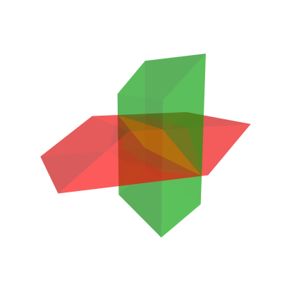
This diagram represents two intersecting hyperplanes. The green and red parallelopipeds represent sections of two hyperplanes in some orientation. It just so happens that they intersect at 90°, but the additional degree of freedom in 4D means that even then, they still can vary in lateral orientation. The yellow square represents a square section of their 2D intersection (note that hyperplanes in 4D, in general, will intersect in a 2D plane).
Hopefully, the analogy with the previous diagram of intersecting planes in 3D is clear.
- quickfur
- Pentonian
- Posts: 2955
- Joined: Thu Sep 02, 2004 11:20 pm
- Location: The Great White North
Re: Visualizing 3-hyperplanes
![]() by quickfur » Thu Jan 23, 2014 1:17 am
by quickfur » Thu Jan 23, 2014 1:17 am
ac2000 wrote:[...] I suppose each of the 3D => 4D spinning objects then rotates around the plane which is a slice in its center or something? But I can't really imagine this 4D rotation behaviour, where things rotate around a plane (instead of an axis), it's just too complicated for me.
[...]
When I first started studying the subject of 4D, I kept confusing myself because I couldn't free myself from understanding rotation as happening around an axis, so I kept running into contradictions when I tried to rotate 4D objects in my mind. Then I started reading about 4D rotations happening around a plane, and it totally boggled my mind -- I could not even begin to understand how something could rotate "around" a plane which extends infinitely in two directions!
The breakthrough for me came when I finally started to understand that rotation (plane rotation, that is, which is the only kind of rotation present in 2D and 3D) is an inherently 2D phenomenon: if you mark a point on a rotating object (in any dimension), it will trace out a circle. Mark another point, and it will trace out another circle, maybe of different radius, but always parallel to other such circles. Since these circles always lie in parallel planes, we can pick one of them as being the representative "plane of rotation", and thus we may understand rotation as happening in some given plane, rather than around some axis (which only works in 3D -- even in 2D there is no such thing as a rotational axis, because any such "axis" that you try to imagine actually protrudes into 3D, and so isn't really within the confines of 2D space!).
This approach to understanding rotation immediately leads to the observation that, since rotation "uses up" two dimensions, if you have a 2D rotation, then the only thing left is a 0D point -- the center of rotation in 2D. Similarly, in 3D, rotation happens around an axis simply because the rotation "uses up" 2 of the 3 dimensions, and therefore you're left with a 1D stationary line -- the rotational axis. This then leads to the prediction that in 4D, you'd have two dimensions leftover, which should produce a 2D stationary plane -- hence we speak of 4D rotations as happening "around a plane". Some further thought then leads to a new kind of rotation in 4D that doesn't exist in lower dimensions: one where you introduce a second rotation in the stationary plane of the first, resulting in a so-called "double rotation" or "Clifford rotation".
But let's not get ahead of ourselves. One of the easiest ways to understand 4D rotations is by projection in 3D. Well, first, let's look at projections of 3D rotations into 2D, to establish a frame of reference:


Now, I know we're all liable to immediately understand these animations in a 3D way, because that's what our brain instinctively and unconsciously does, so we see the square rotating in 3D in various orientations. But let's look at the leftmost animation for a moment. Temporarily "turn off" the 3D interpretation in your mind, and look at it from a purely 2D perspective -- if you like, see it as a 2D array of pixels on the screen that forms what amounts to a morphing quadrilateral. Pretend that you're a 2D creature, confined to the surface of the screen, and you're observing this animating image as an array of 2D pixels. What would you see? You'd see a very strange object, that can't seem to decide what shape to take on. In one moment it's a square, but in the next moment it quickly deforms into a trapezium, and even collapses into a line, then morphs into another trapezium, then back to a square again, and so on.
If somebody were to tell you, as a 2D being, that this morphing object is actually just a perfectly ordinary square doing a perfectly ordinary rotation, you'd call him crazy. How can this crazy, morphing thing even be called a "perfectly ordinary square"??! And it certainly isn't rotating, not in any sense of the word that you'd be familiar with. It's the animation on the right, that's a rotating square: that's what normally happens in 2D! Whereas the first two animations represent something totally foreign to the 2D world. Call them what you will, they are no squares; they are morphing quadrilaterals that are performing impossible feats of turning inside-out!
Well, if we return to 3D, it should be easy to see that actually, these strange morphing impossible quadrilaterals are really just squares rotating in the 3rd dimension.
It is instructive to note that the third animation appears just like a normal 2D rotation, when viewed from a 2Der's POV. That's because it's a rotation in the XY plane, whereas the first two rotations involve the 3rd dimension, the Z axis (they are rotations in the XZ and YZ planes). Furthermore, the first two rotations are identical in appearance except for orientation. So there are really just two appearances of 3D rotations here (at least, this is true if we're talking about principal rotations, that is, those that are aligned with the coordinate axes): the "inside-out" kind, which involve the 3rd dimension, and the "ordinary" kind, which involves only the two dimensions in 2D space.
And now we're ready to take the leap into 4D. Again, we use projections to visualize 4D rotations, this time by projecting 4D into 3D. There are actually six principal 4D rotations, but don't be frightened by their number: in terms of appearance, they really only occur in two classes: an "ordinary" kind, which appears exactly like a 3D rotation, and an "inside-out" kind, which involves the 4th axis. Since we're all already familiar with 3D rotations, we really only need to learn 3 new rotations, those that involve the "inside-out" appearance. So here, for your viewing pleasure, are 3 animations showing how a cube may rotate in 4D in the "inside-out" manner:


Now, before you freak out at the frightening appearance of these rotations, remember how a perfectly ordinary 3D rotation appears so foreign and impossible to a 2Der. What's happening here is exactly analogous to the previous scenario, except that now we're in the position of the 2Der who can't see higher-dimensional space, and so are forced to interpret what's before us at face value -- and we see a hexahedra distorting and contorting in an impossible turning-inside-out kind of way, and it boggles our mind to think that such an impossible feat could represent rotation! But, just as a 3D rotation of a square appears to a 2Der to be an impossible inside-out contortion, but in reality is really just a perfectly normal 3D rotation of a rigid square, so here, these morphing hexahedra are really just rigid cubes doing perfectly normal 4D rotations. They aren't distorting or deforming at all; it's just that they're moving through 4D space, and so the apparent distortion is really just an artifact of the perspective projection used to project them from 4D to 3D so that we can actually see them in motion. (If we were to use slicing, instead, most of the time these cubes would just appear as a stationary square, and every once in a while they pop into a cube, and then collapse instantaneously back into squares again -- we wouldn't be able to trace their motion through 4D, so it wouldn't help us understand exactly how they're rotating through 4D space.)
And perhaps now, we're prepared to understand how things can rotate "around" a plane in 4D. Take the middle cube, for example. Imagine a horizontal plane that bisects it. This particular animation is a bit tricky to work with because I didn't put in any frame of reference in the images, but hopefully it's clear that the cross-section of this horizontal plane with the cube is actually a static square of constant area. Well, except for the one frame where the cube is inverting itself inside-out -- but actually, even in that frame, the actual intersection is still the same square, because the corners of the cube at that point are actually far out along the W axis (the frame where the cube appears as a flat square is when it is exactly 90° to our 3D space). This horizontal plane, therefore, represents the stationary plane of the rotation: points that lie on this plane don't move as the cube rotates. Furthermore, notice how the top/bottom faces of the cube expand and contract as it rotates: the expansion simply means it's moving towards the 4D viewpoint, and the contraction means it's moving away from the 4D viewpoint (remember, this is perspective projection: nearer things appear bigger, and farther things appear smaller). When the top face crosses the horizontal plane in the projection image (but not in 4D space!), it is nearest to the 4D viewpoint, that is, it is displaced by -k units away from the center of the cube, and appears at its largest. Then as it shrinks again, it crosses the horizontal a second time, this time in the smallest appearance -- now it's +k units away from the center of the cube. If you thus trace its motion, you'll see that it's actually moving around the horizontal plane! Remember that the apparent crossing of the horizontal plane does not actually intersect it, because the horizontal plane lies in the 3D space where the stationary center of the cube is, that is, 0 units along the 4th axis, whereas at the apparent crossings, the cube's square face is displaced ±k units along the 4th axis.
So actually, you've already been looking at rotation "around" a plane all along.
It does take some effort to be able to interpret these projection images in the right way, but it's well worth it, since that's when we truly have a glimpse into the nature of 4D space. Once you "grok" how these projection images work, you start discovering all sorts of things about 4D space that somehow just work out to be exactly as the maths describe.
And, to conclude, I can't resist posting the animation of a 4D double rotation:

Remember the horizontal plane we were talking about? Since it's a plane, and wasn't involved in the rotation (that's why it's called a stationary plane), we can add a second rotation in that plane, producing the wondrous double rotation you see above.
 This is a new kind of compound rotation that doesn't exist in 3D or lower, and it features prominently in many 4D objects -- duoprisms, for example, feature a symmetry that directly corresponds with such a rotation. (Don't worry if that just went way over your head... first learn the "simple" plane rotations, then once you've mastered that, this one will come quite naturally. )
- quickfur
- Pentonian
- Posts: 2955
- Joined: Thu Sep 02, 2004 11:20 pm
- Location: The Great White North
Re: Visualizing 3-hyperplanes
![]() by ICN5D » Thu Jan 23, 2014 1:33 am
by ICN5D » Thu Jan 23, 2014 1:33 am
thank you for the detailed introduction and explanation of your notation. I've understood more of it than I had expected. Before, I was always at a total loss when I had seen all those strange notation signs somewhere on the forum.
You're welcome! I felt the same way, when I saw the notation. It seemed impossibly complicated. Then, I don't know, it sort of "clicked" in my head, and I went crazy with it! I started with linear ops, since it was probably the easiest way to generalize into 4D. Then, I took a 5 year hiatus away from this forum, for no particular reason. During that time, I began to create a notation around linear ops, to better understand it. Then, finding more and more ways to create the same shape, I kept adding to the notation, refining it, and I came back to this forum. I think I wanted to finally understand the tiger! And, I did. In the process, I adapted a new kind of operation, the cartesian product, to the existing system. That's why my notation looks horrendously complex. It combines four notations, that I use in four algorithms, to create and define shapes.
You will probably see something that looks like this, floating around: |>| == [ ||^2 , ||-| , |>-2 ]
This is my surface element sequence for a triangle-prism |>| . In the brackets, we have these funny looking symbols: ||^2 , ||-| , and |>-2 . These represent the actual surface panels, and how they are arranged. Once again, I define these shapes as being hollow, in N-1, but I keep the N-1's themselves solid. Does that make sense? The surface panels themselves are solid glass windows, but the shape they build up is hollow.
||^2 : represents two squares attached on an edge
||-| : represents a square paired up with a line, along N+1, triangular pairing
|>-2 : represents two triangles paired together, parallel and separated along N+1, prismic pairing
Picture this: if we place a triangle, point up, on a coordinate graph, where (0,0) is at the center of the triangle, we have certain elements that get skewered, on the X or Y axis. On the x-axis, two attached lines are "skewered" by the x-axis. On the Y, the bottom line and the point ( vertex ) is also skewered, by Y-axis. This is how I "pair up" the surface elements. So, a triangle looks like this: |> == [ |^2 , |-* ]. Where each pair is skewered by an axis, x and y. On the triangle prism, we have two triangles, and three squares. If we remove the triangles and both attached squares, we are left over with a square paired with a line. This is the other way to create a triangle prism, through one of its perspectives. I have spent better part of 6 years developing an algorithm to connect shapes in this manner. I call it the " Perspective Product", and it works on every shape of every dimension.
Now, by extruding a triangle, [ |^2 , |-* ], we also extrude these surface elements. The attached lines |^2, become attached squares ||^2. The line-point pair, |-* become a square-line pair ||-|. Then, we add the two triangles to these connecting sides, |>-2. This is the reductionist method that has always made sense to me. Extruding, tapering, spinning, all can be done individually to a shape's sides, in the respective way.
You may have also seen something that looks like this:
[ |> ] --Z--> [ |> ] == [ |>| ]
-------------------------------------
[ |^2 ] ---> [ |^2 ] == [ ||^2 ]X
[ |-* ] -----> [ |-* ] == [ ||-| ]Y
--------------------------[ |>-2 ]Z
This is the tabular computation that I have created to do these operations. It will probably make more sense now that I have explained it a little better! In the table, you can see the logical flow, where the columns are the surface elements of the shape above the first line. Reading left to right, we are connecting like-shapes together, extruding into a prism along Z. Then, we add the two creating shapes ( the triangles ) back into the final column, which represent the elements of the triangle-prism! This is how I keep track of what's happening to each pairing, highly necessary when getting into 6, 7, 8D. After a while, this can be done mentally ( like mental math ), making 8D not so scary anymore.
An alternative table is the square-line pairing:
[ || ] ---Z---> [ |x ] == [ |>| ] --> square scales down to line of X = triangle-prism
-------------------------------------------
[ |-2 ] -----> [ *-2 ] == [ |>-2 ]X -- > connecting two lines to two points = two triangles
[ |-2 ] -------> [ | ] == [ ||^2 ]Y --> connecting two lines to ONE line == two ATTACHED squares
---------------------------[ ||-| ]Z --> creation elements as last pair, along Z
The interesting, and most important rule about connecting a higher shape to a lower, is a matter of viewing perspective. Connecting a square to a line, along Z, we will be seeing the line differently, depending on the axis of pairing. If we place this line in its " native n-plane ", the x-axis of the 1st dimension, the square, being 2D, will have its x-axis line-pair viewing, and connecting to the line's EDGE, as its two points, " *-2 ". However, the other line-pair, on the y-axis, is looking "down" on the line, from a higher perspective. This Y-line-pair will connect to the ENTIRE line of X.
Just to go beyond 4 and 5D, I want to show you a frightening 6D shape, as created and expressed in my notation. I understand that this is not very elementary! But, I want to show you that 6D isn't that impossible to see. Since you picked up the notation better than you expected, ac2000, let's push the limits a little bit.
Here is the Conindric Trianglinder: it is a cartesian product of two 3D shapes. These will multiply together, and make a 6D shape. You can think of it as an entire cone branching off of every point, on and within a triangle prism. This is pretty much what cartesian products do. At each corner of this 6D triangle-prism structure, there is an entire cone. Along each edge, there is a cone-prism ( coninder ). Spread out along each 2-D panel, is a cone-diprismic space, if we remove the edges and corners. Connecting all of the curved surfaces together will create a single torus, the rolling surface of this crazy thing.
Cone x Triangle-Prism == Conindric Trianglinder
|O>[|>|] and |>|[|O>]
* Surface elements of a triangle-prism, |>| : [ ||^2 , ||-| , |>-2 ]
* Surface elements of a Cone, |O> : [ |(O) , |O-* ] --> " |(O) " stands for " line-torus " or line extruded along the path of a circle. " |O-* " stands for " circle paired with point "
The symbol pairs in brackets denote them as being the final linear operations that you would stick onto the ends of the non-bracketed shape. A square product can be simplified as two extrusions. A triangle product cannot be done with linear ops, so it is to remain in its brackets. |>[||] == |>|| , |>[|>] =/= |>|>
[ |>| , |O> ] == |>|[|O>]
---------------------------------------------
[ ||^2 ] , |O> == [ |O>||^2 ]X
[ ||-| ] , |O> == [ |O>||--|O>| ]Y
[ |>-2 ] , |O> == [ |O>[|>]-2 ]Z
|>| , [ |(O) ] == [ |>||(O) ]WV
|>| , [ |O-* ] == [ |>||O--|>| ]U
So, in the end result, we get these crazy shapes:
|O>||^2 : an attached pair of cone-diprisms
|O>||--|O>| : a cone-diprism paired with a coninder
|O>[|>]-2 : a prismic pair of contrianglinders
|>||(O) : a torus of a triangle-diprism
|>||O--|>| : a cyltrianglinder-prism connects to a triangle-prism. A special kind of pairing, where a curved shape scales down to an uncurved ( orthogonal) shape. This is the staple of the coninder, where a cylinder scales to a line, as one of the perspectives. The first case of a torus connecting to its own subshape ( minor radius)
It has SEVEN side panels. Six flat, one continuous rolling surface. This means that a Conindric Trianglinder can be rotated around, in 6D, and looked at it through its different side panels:
* |O>||--|O>| : Looking through one of its three Cone-Diprism sides. Triangluar perspective, an N-Prism scales down to shape N.
* |O>[|>]-2 : Looking through one of its contrianglinder sides. Prismic perspective, two identical contrianglinders connect together, or we can extrude a 5D contrianglinder into 6D
* |>||O--|>| : Looking through its only cyltriandyinder ( cyltrianglinder-prism) side. The "conindric" perspective.
I have been meaning to elaborate on this hiddeous-looking notation system of mine. Just now had the clarity to do it, at a great opportunity for everyone!
-Philip
It is by will alone, I set my donuts in motion
- ICN5D
- Pentonian
- Posts: 1135
- Joined: Mon Jul 28, 2008 4:25 am
- Location: the Land of Flowers
Re: Visualizing 3-hyperplanes
![]() by Klitzing » Thu Jan 23, 2014 11:28 am
by Klitzing » Thu Jan 23, 2014 11:28 am
ICN5D wrote:Klitzing: thank you for the kind words!
You are welcome!
I like to describe shapes by their hollow form, and associate the N-1 elements as being surface panels paired together, on a respective axis.
* Generalization: For an N-D shape, there are (N-1)D flat surface panels joined together, encasing a central void of N-D space.
This means a 3D shape has 2D surface panels encasing a central void of 3D space. A 4D shape has 3D "flat" surface panels encasing a void of 4D space. A 5D shape has "flat" 4D surface panels, encasing a central void of 5D space, etc.
This is NOT the view of polytopists. A D-dimensional polytope generally has ellements of D+2 different dimensions: the single (-1)-dimensional nulloid (Wendy likes to call that one "essence" instead) - that one is arguable, but serves well in more technical contextes -, the 0-dimensional vertices, the 1-dimensional edges, ..., the (D-1)-dimensional facets, and the single D-dimensional bulk (equivalent to area resp. volume). - Your view thus comes closer to what tesselationists would do. Considering only the tesselation of the surface, with nothing below nor above.
Consider Eulers formula for polyhedra: V-E+F = 2, i.e. the number of vertices, reduced by the number of edges, augmented by the number of faces always will be 2 - provided no holes and other strange stuff would occur. A similar formula for even dimensions would result in a value zero (e.g. 4D: V-E+F-C = 0, where C = number of cells). This alternation between 2 and 0 in fact just reflects the omission of those 2 additional unique elements: on rather should sum that way:
sum from d=-1 to d=D on (-1)^d N_d = 0
where N_d is the number of subelements of dimension d.
Within spherical geometry, esp. for polytopes, whose facets kind of circle around some center point, (the "orientable" ones) one usually is used to consider the body as well. Within flat euclidean space and in hyperbolic geometry one more often is using a tesselating point of view. But euclidean tilings might be re-used within euclidean honeycombs for facets. And similarily both euclidean tesselations, and hyperbolical ones (with lower or equal absolute value of curvature) can be re-used in hyperbolic tesselations as subelements. This is just what Wendy then calls horo- resp. bollo-tiles, i.e. infinite polytopal elements with euclidean or hyperbolic curvature. Then those mere tesselations get added by some body below, and those thus get re-considered as (infinite) true polytopes again.
--- rk
- Klitzing
- Pentonian
- Posts: 1638
- Joined: Sun Aug 19, 2012 11:16 am
- Location: Heidenheim, Germany
Re: Visualizing 3-hyperplanes
![]() by Klitzing » Thu Jan 23, 2014 12:37 pm
by Klitzing » Thu Jan 23, 2014 12:37 pm
ICN5D wrote:I posted a decent definition of the spin/lathe for Wendy some time ago, here it is. However, words can only do so much, I need to illustrate it! :
In reality I suppose there are two ways to lathe non-toric shapes:
- Hold a shape in place and rotate into N+1 around an axis that divides the shape in half : "lathe"
- Hold a surface element in place ( most likely one on the previous constructed axis ) and rotate into N+1 : "flip"
The "flip" can create some tegum products, as in the flip of a triangle creates a bicone, the tegum product of a circle and digon.
Okay, lathe uses some internal section which contains the body center, while flip uses some surface element, a facet.
The part I want to focus on is the lathe around the center: When a shape spins into N+1, some of the panels are moving around in a circle, while the rest sit still and rotate. During an N+1 lathe, an N-dimensional shape can be cut in half by an N-1 dimensional shape ( or surface element for that matter ).
Generally you'd speak of hypersurface here.
Well, a square would be "cut into half" by any line containing the center point. Both half then come out to be congruent, for any such cut! Similarily a cube will be "cut into half" by any plane containing its body center. Again both parts come out to be congruent, generally! - That is, your "definition" of the to be chosen axis still is not precise enough, in order to define a unique action of "spin".
(Sure, I can see your specific choices within many of your provided examples, but I was - and still am - missing the general rule to be applied.)
E.g. this so far provided "rule" does not pretend to rotate a square around its diagonal (providing some dicone), whereas you want to get a cylinder! - And the higher the dimension, even worse cases could arise.
So let me shorten that proces of iterated redefinitions a bit. It kind of looks like you want to choose the cutting hyperplane according to:
- case "|...|O": take the (centered) hyperplane to be parallel to the bases of that prism - thus being solved
- case "|...>O": - still not uniquely defined: Solved for "|>O": as here the last tapering height has to be contained in that hyperplane. Both that height and that hyperplane are 1-dimensional here. Thus in this case the spin is well defined, providing the desired cone. But in general that height remains 1-dimensional, but the hyperplane becomes (D-1)-dimensional. Thus your "rule" then is already better than merely using the center point, but still not unique.
- case "|...OO": - ???
Further, the provided examples of your birthday mail (btw. belated congratulations!) seem to imply that
- trailing symbols "|...|O" do commute (i.e. = "|...O|"), and similarily
- trailing symbols "|...O>" would commute as well (i.e. = "|...>O"), whereas
- "|...|>" generally is different from "|...>|".
(If positive, then we might move all the "O"s e.g. to the right end always, in order to get some unique standardized symbol for the respective shapes.)
--- rk
- Klitzing
- Pentonian
- Posts: 1638
- Joined: Sun Aug 19, 2012 11:16 am
- Location: Heidenheim, Germany
Re: Visualizing 3-hyperplanes
![]() by ICN5D » Thu Jan 23, 2014 6:42 pm
by ICN5D » Thu Jan 23, 2014 6:42 pm
Well, you're right about the spin definition needing to be better clarified. This is ultimately the first time I tried to really explain it. It's more an intuitive feeling I got when spinning n-cubes around. I extrapolated the way certain elements stayed in place ( so to speak ) , and saw only ONE pair tracing out a circular path, with shapes that have only one spin op.
Rotations will happen around an N-1 hyperplane. Quickfur pointed this out in the above posts. This is what I mean by " N-1 dividing plane". In spinning around an N-1 division, I always mean along an axis/plane/realm, not diagonally ( even though it is still a valid way to do so, I haven't delved into that specific way yet). I noticed a cool trick with certain projections, when a spin is applied. If the shape is drawn on paper, there will be some vertical lines, horizontal lines, and diagonals. The horizontals are transformed in a special way during a spin. Illustrations will be key here, but I'm at work until 18:30, so we'll have to wait!
Picture the 2D projection of a cube, ||| : square inside a square. In this drawing, there will be 4 horizontal lines, 4 vertical, 4 diagonal. When we spin this cube, into 4D, it will trace out a cubinder, |||O . A special shortcut method to transform the "square inside square" drawing into the cubinder, is to turn all 4 horizontal lines into circles ( flattened ovals, more precisely ). This drawing will then become a projection of the cubinder: " cylinder inside cylinder". The sequence ||O| stands for extruding a cylinder, which is also going to make for a "cylinder inside cylinder" projection.
Same with the spin of a triangle prism: viewing through a square panel, we see a square scaling to a line. This line at the far side should be oriented horizontally. By spinning this triangle prism, we can turn the horizontal lines into circles, and make the " cylinder to circle" projection of the cyltrianglinder. Note how in each case we are transforming a 2-D drawing into a 3D " shadow projection", but still drawn on 2-D paper, for simplicity.
Now, lets consider the cylindrone: ||O>. Since we pointed out how the spin commutes, the sequence can also be ||>O, which suggests that spinning a square pyramid makes a cylindrone. How can this be?? Let's view a square pyramid through its square side: square as near side, point as far "side", connected by 4 triangles. Now, once again, turn the horizontal lines into circles, and we have a projection of a cylindrone, looking through its cylinder side.Two of the original triangles are spun into cones, the other two become a triangle torus, while the base-square spins into a cylinder. Also what we get when tapering a cylinder.
Now, when spinning even higher shapes, with a crazy number of side panels paired up, I noticed that, with one spin op, only ONE pair of elements always end up becoming the new torus rolling side. The rest, no matter how many more there are, always end up staying in place, and rotating, NOT becoming a rolling side. Just like the hypercube spins: there is always one torus, and the rest are n-cylinders ( the flat sides). This is my intuitive spidey sense when it comes to how to spin these things around.
For any kind of prism: the last-constructed axis, that skewers the prismated elements, will be the rotating axis. These identical end caps trace out a circular path and become the new torus rolling side. The subshape of this torus is the original, prismated element.
For any kind of orthogonal pyramid-type shape: the second last is in motion. Spinning a triangle is probably the best way to see how this would work. Since there are no prismically paired sides, the axis that we tapered along can be the dividing axis. Rotation around this axis will turn the bottom line into a circle, the connecting lines into a single rolling surface. This is the principle rule with tapered shapes: one of the CONNECTING pairs, between the base and vertex, will become the new toric rolling side.
For n-spheres: they occupy their space evenly, with no well defined edges or panels to pair up. So, in a ways, spinning the n-sphere will sort of "torus-ify" the entire surface, into another perpendicular extension with circular symmetry. In whatever way you want to do it, adding spins to an n-sphere will create the N+1 sphere. Spinning a cone |O>, where the base is a circle, should be treated as a spherical-type shape. This is what I meant by " spheric lathe". The rotation of this cone, which has a symmetrical connecting side, between base-vertex pair, will become the sphone. Once again, the spins commute: |O>O == |OO> == |>OO .
The toric lathe/spin is where we spin a shape with a curved surface AND flat elements, most likely an N-Cylinder. We can spin a cylinder two different ways: prismic spin makes the duocylinder, ||O --> ||OO . The toric spin of a cylinder will make the spherinder: ||O --> Om == |OO|.
I will probably provide some cool pics of this process when I get a chance.
-Philip
It is by will alone, I set my donuts in motion
- ICN5D
- Pentonian
- Posts: 1135
- Joined: Mon Jul 28, 2008 4:25 am
- Location: the Land of Flowers
Re: Visualizing 3-hyperplanes
![]() by quickfur » Thu Jan 23, 2014 9:36 pm
by quickfur » Thu Jan 23, 2014 9:36 pm
ICN5D wrote:[...]Now, lets consider the cylindrone: ||O>. Since we pointed out how the spin commutes, the sequence can also be ||>O, which suggests that spinning a square pyramid makes a cylindrone. How can this be??
Simple. First define H to be a plane that bisects the pyramid such that it intersects the apex, and cuts the base into two rectangles. Now rotate the square base of the pyramid around this plane H. Since H is by construction the stationary plane of the rotation, and the apex lies on it, the apex will remain unchanged. The rotating square traces out a cylinder, and if you consider each of the square sections of the pyramid if you intersect it with various planes parallel to the base, you'll see that each such section traces out a cylinder under this rotation, until it reaches the stationary apex. Therefore, the resulting shape is just a stack of cylinders of decreasing size, converging upon a point, that is, it's a cylindrone.
This isn't the only way to spin a square pyramid, however. There are many other ways, all of which yield various different shapes.
Consider if you keep the base of the pyramid fixed, and rotate its apex around the plane of this base. The apex will trace out a circle, while the triangular faces will trace out triangular torus-shapes (with a zero-radius hole -- the cross section is a rhombus). There are 4 such torus shapes that connect the square base to the circle, so this shape is actually the square-circle tegum (the dual of a cubinder).
Furthermore, if you keep the apex fixed, and let G be the plane tangent to the apex and parallel to the base, then if you rotate the pyramid around G, the square base will trace out a cubinder, while the apex remains fixed, and thus the result will be a cubinder (the apex becomes interior to the result -- topologically, this would be a cubindrical pyramid but unless the apex is displaced in the 5th direction it will be degenerate (5D height of zero)).
Yet another way is to bisect the pyramid with a vertical plane that intersects the apex and cuts the base into two isosceles triangles. Rotating about this plane causes the square base to rotate about its diagonal, thus tracing out a shape made of two cones joined at their bases. Along with the apex, you get a pyramid of this base shape of two cones joined at their bases.
So you see, it's ambiguous to represent a cylindrone as a spinning of a square pyramid. Such a construction has multiple interpretations! So your spin operator only commutes under certain conditions, and is ambiguous in the general case.
- quickfur
- Pentonian
- Posts: 2955
- Joined: Thu Sep 02, 2004 11:20 pm
- Location: The Great White North
Re: Visualizing 3-hyperplanes
![]() by quickfur » Thu Jan 23, 2014 9:39 pm
by quickfur » Thu Jan 23, 2014 9:39 pm
ICN5D wrote:[...] Rotations will happen around an N-1 hyperplane. Quickfur pointed this out in the above posts. This is what I mean by " N-1 dividing plane". [...]
Be careful there. In order to be able to rotate around an (n-1)-hyperplane, the rotation must take place in (n+1) dimensions. Any n-dimensional rotation cannot happen around an (n-1)-hyperplane; it rotates rather around an (n-2)-hyperplane. But what you said makes sense in the context of constructing (n+1)-dimensional objects out of n-dimensional objects, so in that sense it's not wrong.

- quickfur
- Pentonian
- Posts: 2955
- Joined: Thu Sep 02, 2004 11:20 pm
- Location: The Great White North
Re: Visualizing 3-hyperplanes
![]() by ICN5D » Fri Jan 24, 2014 1:38 am
by ICN5D » Fri Jan 24, 2014 1:38 am
Yep, that's what I meant. During an N+1 lathe, an N-dimensional shape can be cut in half by an N-1 dimensional hyperplane. Or, to put it another way, rotating an N-D shape around a stationary (N-1)-cube. The latter is the way you said it, and I like it better.
Thanks for elaborating on my answer to the "spin of square pyramid" question. I may have asked it rhetorically, but it did deserve a little more explanation. And, you're right, there are MANY ways to spin it, depending on the orientation of the stationary square of rotation.
I guess I could call that the "flip" of the square pyramid. I hadn't really looked much into this motion, but that's interesting that it creates square-circle-tegum.
About this whole "spin operation" business: I can't really say that I created it, but more precisely discovered it, as a linear way to create cartesian products with circles. I'm inclined to call that a "circle product" ( n-cylinders ), where we can also have square-product ( n-diprisms ), and triangle-product ( n-trianglinders ).
The linear way to make a circle-product, with an N-D shape, is by extruding along N+1, then holding in place and rotating into N+2. By deriving the surface elements of many, many shapes that had spins, and searching for patterns, I soon found this phenomenon. In the single-spin cases, it was only one pair of elements on some axis that got the torus operation. The rest of the elements, after the spin, got the circle-product. The number of spins is directly proportional to the number of curved rolling side torii. This evolved into my definition of the spin, that originally got derived from cartesian products. So, hopefully it won't be so scary anymore
-Philip
Thanks for elaborating on my answer to the "spin of square pyramid" question. I may have asked it rhetorically, but it did deserve a little more explanation. And, you're right, there are MANY ways to spin it, depending on the orientation of the stationary square of rotation.
.Consider if you keep the base of the pyramid fixed, and rotate its apex around the plane of this base. The apex will trace out a circle, while the triangular faces will trace out triangular torus-shapes (with a zero-radius hole -- the cross section is a rhombus). There are 4 such torus shapes that connect the square base to the circle, so this shape is actually the square-circle tegum (the dual of a cubinder)
I guess I could call that the "flip" of the square pyramid. I hadn't really looked much into this motion, but that's interesting that it creates square-circle-tegum.
About this whole "spin operation" business: I can't really say that I created it, but more precisely discovered it, as a linear way to create cartesian products with circles. I'm inclined to call that a "circle product" ( n-cylinders ), where we can also have square-product ( n-diprisms ), and triangle-product ( n-trianglinders ).
The linear way to make a circle-product, with an N-D shape, is by extruding along N+1, then holding in place and rotating into N+2. By deriving the surface elements of many, many shapes that had spins, and searching for patterns, I soon found this phenomenon. In the single-spin cases, it was only one pair of elements on some axis that got the torus operation. The rest of the elements, after the spin, got the circle-product. The number of spins is directly proportional to the number of curved rolling side torii. This evolved into my definition of the spin, that originally got derived from cartesian products. So, hopefully it won't be so scary anymore
-Philip
It is by will alone, I set my donuts in motion
- ICN5D
- Pentonian
- Posts: 1135
- Joined: Mon Jul 28, 2008 4:25 am
- Location: the Land of Flowers
Re: Visualizing 3-hyperplanes
![]() by quickfur » Fri Jan 24, 2014 3:27 am
by quickfur » Fri Jan 24, 2014 3:27 am
ICN5D wrote:[...]
Thanks for elaborating on my answer to the "spin of square pyramid" question. I may have asked it rhetorically, but it did deserve a little more explanation. And, you're right, there are MANY ways to spin it, depending on the orientation of the stationary square of rotation..Consider if you keep the base of the pyramid fixed, and rotate its apex around the plane of this base. The apex will trace out a circle, while the triangular faces will trace out triangular torus-shapes (with a zero-radius hole -- the cross section is a rhombus). There are 4 such torus shapes that connect the square base to the circle, so this shape is actually the square-circle tegum (the dual of a cubinder)
I guess I could call that the "flip" of the square pyramid. I hadn't really looked much into this motion, but that's interesting that it creates square-circle-tegum.
Those are just a few of the ways of spinning a square pyramid. There are more ways. Here's one more: rotate it around the plane of one of its triangular faces. Under this rotation, its square base traces out a cone-prism (extruded cone), and the part around its apex traces out a kind of cylinder pyramid. So the result is a shape made from joining a cone prism to a cylinder pyramid at the cylinder cell.
It's also possible to spin the square pyramid around a plane tangent to one of its apex-to-base edges. I haven't worked out what is the result, but if you spin a tetrahedron in this way, it produces a cylinder bipyramid.
All kinds of interesting shapes can be produced by this kind of "lathing" process.
About this whole "spin operation" business: I can't really say that I created it, but more precisely discovered it, as a linear way to create cartesian products with circles. I'm inclined to call that a "circle product" ( n-cylinders ), where we can also have square-product ( n-diprisms ), and triangle-product ( n-trianglinders ).
The linear way to make a circle-product, with an N-D shape, is by extruding along N+1, then holding in place and rotating into N+2. By deriving the surface elements of many, many shapes that had spins, and searching for patterns, I soon found this phenomenon. In the single-spin cases, it was only one pair of elements on some axis that got the torus operation. The rest of the elements, after the spin, got the circle-product. The number of spins is directly proportional to the number of curved rolling side torii. This evolved into my definition of the spin, that originally got derived from cartesian products. So, hopefully it won't be so scary anymore
-Philip
Ah, I see what you're getting at. If you're going from n dimensions to (n+2) dimensions, then it's possible to define a unique "spin" operator, which essentially boils down to the Cartesian product with a circle.
- quickfur
- Pentonian
- Posts: 2955
- Joined: Thu Sep 02, 2004 11:20 pm
- Location: The Great White North
Re: Visualizing 3-hyperplanes
![]() by ICN5D » Fri Jan 24, 2014 4:16 am
by ICN5D » Fri Jan 24, 2014 4:16 am
Yes, but that's just the spin of a prism. The spin of a triangular shape ( where we see >O and O> ) is more around the dividing n-cube that sits parallel to the last constructed axis of tapering. Sure there are more ways, but I am focusing on the specific one that turns triangles into cones, square pyramids into cylindrones, cones into sphones. That method is transferable to any tapertope. Even if the shape has both a prism and triangular perspective, like the triangle prism. Applying the rule will still make the triangle ends whip around into 4D, along the circular path, to make the triangle torus.
But, perhaps one has to be more stringent in choosing which of these element pairs will become the new torus. I guess we sort of have to "search" for it in a ways, if not familiar with a shape's surface elements. As in, not trying to connect one of the square panels into the torus, but identifying that the triangle pair should be the one. Of course, this is only according to the spin method I'm defining.
-Philip
It is by will alone, I set my donuts in motion
- ICN5D
- Pentonian
- Posts: 1135
- Joined: Mon Jul 28, 2008 4:25 am
- Location: the Land of Flowers
Re: Visualizing 3-hyperplanes
![]() by quickfur » Fri Jan 24, 2014 4:58 am
by quickfur » Fri Jan 24, 2014 4:58 am
ICN5D wrote:Yes, but that's just the spin of a prism. The spin of a triangular shape ( where we see >O and O> ) is more around the dividing n-cube that sits parallel to the last constructed axis of tapering. Sure there are more ways, but I am focusing on the specific one that turns triangles into cones, square pyramids into cylindrones, cones into sphones. That method is transferable to any tapertope. Even if the shape has both a prism and triangular perspective, like the triangle prism. Applying the rule will still make the triangle ends whip around into 4D, along the circular path, to make the triangle torus.
Even with a square pyramid, there are at least two highly-symmetric ways to choose the plane to rotate around. One is a vertical plane that bisects the base into two rectangles, which produces a cylindrone; the other is a vertical plane the bisects the base into two isosceles triangles, which will produce a circle-bipyramid-pyramid (i.e. pyramid of two cones joined base-to-base). Both planes of rotation are parallel to the previous axis of tapering (assuming the construction square -> square pyramid via tapering).
To be fair, though, if we choose a predetermined frame of reference, we could say the cylindrone is produced through spinning a square pyramid, whereas the circle-bipyramid-pyramid is produced through spinning a diamond pyramid (diamond = dual of square, i.e., a square rotated 45°, but it's helpful to distinguish between them since, in a fixed frame of reference, they play distinct roles when brought into higher dimensions).
Be aware though, if you take this approach, that the same shape(s) may produce different results depending on how you analyze them; e.g., an octahedron can be analyzed either as a triangle antiprism (with two opposite faces aligned along a coordinate axis), a rectified tetrahedron (aligned according to tetrahedral symmetry), the dual of a cube (same as diamond bipyramid), or a bipyramid of a square (rotated 45° in the horizontal plane). Each of these analyses will yield a different result if your operator is aligned to a particular frame of reference. Similarly, different results may be obtained in 4D depending on whether you consider the 24-cell as a 24-cell (in its own symmetry group), a rectified 16-cell (reduced symmetry), or a dual 24-cell. The 16-cell could similarly be analyzed either as the dual of the tesseract or the alternated tesseract (both are congruent, but have different orientations).
But, perhaps one has to be more stringent in choosing which of these element pairs will become the new torus. I guess we sort of have to "search" for it in a ways, if not familiar with a shape's surface elements. As in, not trying to connect one of the square panels into the torus, but identifying that the triangle pair should be the one. Of course, this is only according to the spin method I'm defining.
[...]
If you have an unambiguous way of choosing the plane of rotation, then it works. But this may be more tricky than it first appears, as I point out above.
- quickfur
- Pentonian
- Posts: 2955
- Joined: Thu Sep 02, 2004 11:20 pm
- Location: The Great White North
Re: Visualizing 3-hyperplanes
![]() by ICN5D » Fri Jan 24, 2014 7:34 am
by ICN5D » Fri Jan 24, 2014 7:34 am
Now that I got to thinking about it, there is a predictable rule that can be applied to which axes are stationary during the spin. Once again, these stationary axes lie, or are "skewered ", by the same plane as the dividing n-cube. This always leaves one axis left, to become the moving ( torus-making ) axis. In a construction sequence, the spin operator can be paired with another spin, a taper, or extrude. This adjacent operator defines what kind of spin we do. That is, which axes are stationary and which is the moving one. Since there is always one moving axis, identifying it will in a sense define the spin-type. Adjacent as in previous operator to the left.
Another way to visualize a spin is with another linear op. You can think of the spin as a 0-D operation, where the shape isn't moving anywhere, but rotating in place into N+1. When we extrude or taper, the shape is moving along N+1. By tapering, we are still shrinking while extruding. Take the spin+extrude, we are essentially rotating while extruding. No matter if we spin or extrude first, the result is the same. Or, look at the spin+taper: shrinking to a point while rotating. Taper or spin first, it still makes the same complex 2-D motion.
For some shapes, like the cylindrone ||O> , the spin can commute to all three positions after the first line. We can call it the "quantum spin", because it exists in simultaneous places at once: |O|> , ||O> , ||>O , and still make the same thing. However some shapes cannot be rearranged, like the cyltrianglinder |>|O. I like to call this a "prime" shape. All of the tapertopes are prime, but few with a spin operator.
* If the spin is paired with an extrude, then we treat this spin as the " Prismic Spin", where the last constructed axis is in motion. The last constructed axis is the one we extruded shape Q along to create a prism, the Q-Prism. The prismic spin, by definition, will make the Q-shaped end caps move around like standing on the equator, and follow along the path of a circle, to make a Q-torus. All of the rest of the element pairs skewered by the stationary axes will sit in place and spin.
* If the spin is paired with a taper, then we treat this spin as the " Triangular Spin", where the second-last constructed axis is in motion. This rule will allow the triangle to spin properly into a cone, and not make some terrible-looking overlapping shape. It also works with the cylindrone, one of the triangle pairs are in motion, and not the base overlapping the vertex.
* If the spin is paired with sequence of spins, then the ambiguity doesn't matter. By examining the way a circle can spin into a sphere, spinning a sphere around a plane will add another 90 degree circular extension to the existing two, making a glome. One can spin an n-sphere from any dividing angle. However, this does not hold up when we add a spin op to the cylinder form of ||O. This is why I said sequence of spins, if there is another extrude ( other than the "starting line"), the rule changes.
* In the case of spins pairing up in the company of extrusions, this is called the " Toric Spin". This kind of spin can only be applied to an n-cylinder. All n-cylinders have flat and curved sides. The curved side(s) are always a toratope of some kind, where the major radius of this toratope traces out the rolling surface. The major radius will have a circular symmetry of an n-sphere. This n-sphere-radius will occupy an n-plane. The toric spin happens when the single moving axis is on this n-plane, of the major radius. Spinning will rotate the n-sphere property, and trace out an (n+1)-sphere major radius, while the other axes are stationary. Even if the major radius' n-plane had a stationary axis, due to the circular symmetry and relaxing of abiguity when spinning n-spheres, it won't matter. So, the Toric spin of a cylinder will make a spherinder |OO| and ||OO , the Prismic spin will make a duocylinder |O|O . The Toric spin of a cyltrianglinder, |>|OOm will create the sphentrianglinder, or |OO[|>], written in its cartesian product form. The spin of a duocylinder can be done by a toric spin. It will create the cylspherinder, |O|OO and |OO|O .
* The Trianglindric spin is more abstract, and doesn't happen until in 4D, with the cyltrianglinder. It can only be applied to n-trianglinders, or shapes that are cartesian products with triangles. This spin treats the triangle frame like a regular 2D triangle, and rotates around into N+1 tracing out a cone-like shape.
So, should I be calling this an "orthogonal spin" , where I don't mean diagonal? I'm not sure how to phrase it, any way it takes to mean " non-diagonal".
-Philip
Last edited by ICN5D on Fri Jan 24, 2014 8:40 am, edited 1 time in total.
It is by will alone, I set my donuts in motion
- ICN5D
- Pentonian
- Posts: 1135
- Joined: Mon Jul 28, 2008 4:25 am
- Location: the Land of Flowers
Re: Visualizing 3-hyperplanes
![]() by ICN5D » Fri Jan 24, 2014 8:00 am
by ICN5D » Fri Jan 24, 2014 8:00 am
I acknowledge that there are other ways to spin things. Diagonally, what have you. But, those methods and motions are currently outside of this notation's ability, for now. Perhaps I will incorporate it at some point. They are all still real and valid ways to spin something. But, rotating something by 45 degrees cannot be described in the current notation. Those crazy looking shapes that are truncations and such are pretty wild, and no doubt they hold academic merit. It's a continuing work in progress. Right now, I'm working on an adaptation to Marek's slicing algorithm, in my toratope notation. I'm going to have to create a new system and algorithm, so that'll probably take up some time. After seeing the tiger, I'm curious about the cylspherintigroid and crazy stuff like that. Starting with cuts are probably the best way to "see" holes in higher dimensions. That, and understanding their meat-and-bone structure.
It is by will alone, I set my donuts in motion
- ICN5D
- Pentonian
- Posts: 1135
- Joined: Mon Jul 28, 2008 4:25 am
- Location: the Land of Flowers
Re: Visualizing 3-hyperplanes
![]() by Klitzing » Fri Jan 24, 2014 2:59 pm
by Klitzing » Fri Jan 24, 2014 2:59 pm
quickfur wrote:ICN5D wrote:But, perhaps one has to be more stringent in choosing which of these element pairs will become the new torus. I guess we sort of have to "search" for it in a ways, if not familiar with a shape's surface elements. As in, not trying to connect one of the square panels into the torus, but identifying that the triangle pair should be the one. Of course, this is only according to the spin method I'm defining.
[...]
If you have an unambiguous way of choosing the plane of rotation, then it works. But this may be more tricky than it first appears, as I point out above.
This exactly was my point then!
And only having solved that task, we get ready to investigate whether >O always commutes into O>, resp. |O always commutes into O|.
Alternatively, but then less surprising, you might choose to have exactly those commuting processes, and thus derive your specific choice accordingly.
--- rk
- Klitzing
- Pentonian
- Posts: 1638
- Joined: Sun Aug 19, 2012 11:16 am
- Location: Heidenheim, Germany
125 posts
• Page 1 of 5 • 1, 2, 3, 4, 5
Return to Higher Spatial Dimensions
Who is online
Users browsing this forum: No registered users and 41 guests